TTF300 FIELD-MOUNT TEMPERATURE TRANSMITTER | OI/TTF300-EN REV. I 41
9 Commissioning
General
In case of corresponding order the transmitter is ready for
operation after mounting and installation of the connections.
The parameters are set at the factory.
The connected lines must be checked for firm seating. Only
firmly seated lines ensure full functionality.
Checks prior to commissioning
The following points must be checked before commissioning the
device:
• Correct wiring in accordance with Electrical connections
on page 29.
• The ambient conditions must correspond to the
information given on the name plate and in the data
sheet.
Communication
HART® Communication
Note
The HART® protocol is an unsecured protocol, as such the
intended application should be assessed to ensure that these
protocols are suitable before implementation.
Communication with the transmitter takes place using the HART
protocol. The communication signal is modulated onto both
wires of the signal line in accordance with the HART FSK ‘Physical
Layer’ specification.
The HART modem is connected at the signal line of the current
output via which power is also supplied via the power supply
unit.
The device is listed with the FieldComm Group.
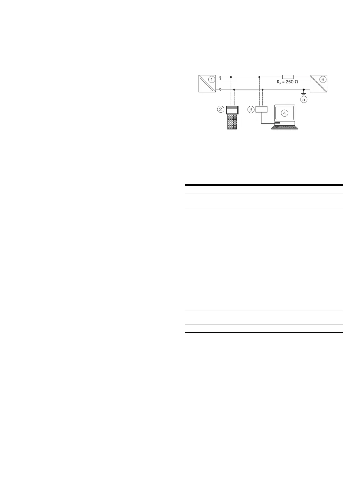
Transmitter
Handheld terminal
HART® modem
PC with Asset Management Tool
Grounding (optional)
Power supply unit (process
interface)
B
load resistance
(if necessary)
Figure 31: Example of HART® interface connection
-ID*
0x004B (0x000B),
SW-Rev.: 03.00 (corresponds to HW-Rev.: 02.00
HART 5.9 and HART 7.6, can be switched via
LCD indicator with configuration function
Tools
HART commands
ordered: HART 7.6.
SW-Rev.: 01.03:
HART 5.1 and HART 7, switchable via DIP switch.
Default, if nothing else ordered: HART
5.1.
-Rev.: 01.01:
HART 5.1, previously HART 5.
On device using LCD indicator
* From SW-Rev.: 03.01.00, previously see brackets

 Loading...


