40 TTF300 FIELD-MOUNT TEMPERATURE TRANSMITTER | OI/TTF300-EN REV. I
… 8 Electrical connections
… Electrical data for inputs and outputs
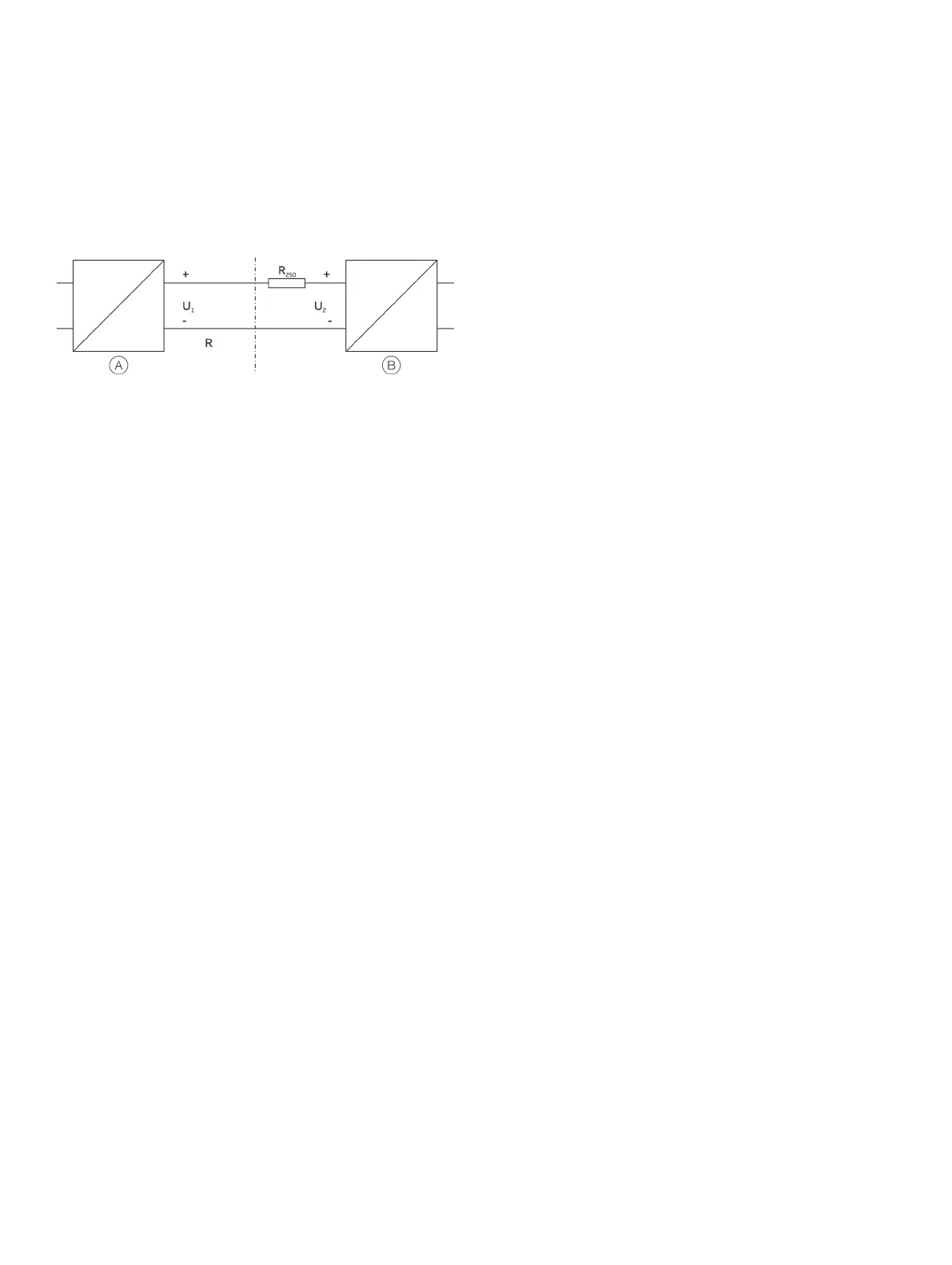
Voltage drop on the signal line
When connecting the devices, note the voltage drop on the
signal line.The minimum supply voltage on the transmitter must
not be undershot.
Transmitter
Supply isolator / DCS input with
supply / segment coupler
Figure 30: HART load resistance
Minimum supply voltage on the transmitter
2min
:
Minimum supply voltage of the supply isolator
/
Line resistance between transmitter and supply isolator
Resistance (250 Ω) for HART functionality
Standard application with 4 to 20 mA functionality
When connecting these components, observe the following
condition:
U
1min
≤ U
2min
- 22 mA x R
Standard application with HART functionality
Adding resistance R
250
increases the minimum supply
voltage U
2min
: U
1min
≤ U
2min
- 22 mA x (R + R
250
)
For HART functionality, use supply isolators or DCS input cards
with a HART mark.If this is not possible, a resistance of ≥ 250 Ω
(< 1100 Ω) must be added to the interconnection.
The signal line can be operated with / without grounding.When
establishing a ground connection (minus side), make sure that
only one side of the terminal is connected to the equipotential
bonding.
For further information on the revision of the standard HART
protocol and on switching options, see HART® Communication
on page 41 and Hardware settings on page 44..
Power supply – PROFIBUS / FOUNDATION Fieldbus
Supply voltage
Non-Ex application:
U
S
= 9 to 32 V DC
Ex-applications with:
U
S
= 9 to 17 V DC (FISCO)
U
S
= 9 to 24 V DC (Fieldbus Entity model I.S.)
Current consumption:
≤ 12 mA
Standard application with PROFIBUS PA and FOUNDATION
Fieldbus H1 functionality
During hookup, the following condition should be complied with:
U
1min
≤ U
2min
− 12 mA x R

 Loading...


