32 TTF300 FIELD-MOUNT TEMPERATURE TRANSMITTER | OI/TTF300-EN REV. I
… 8 Electrical connections
… Shielding of the sensor connecting cable
Additional examples for shielding / grounding
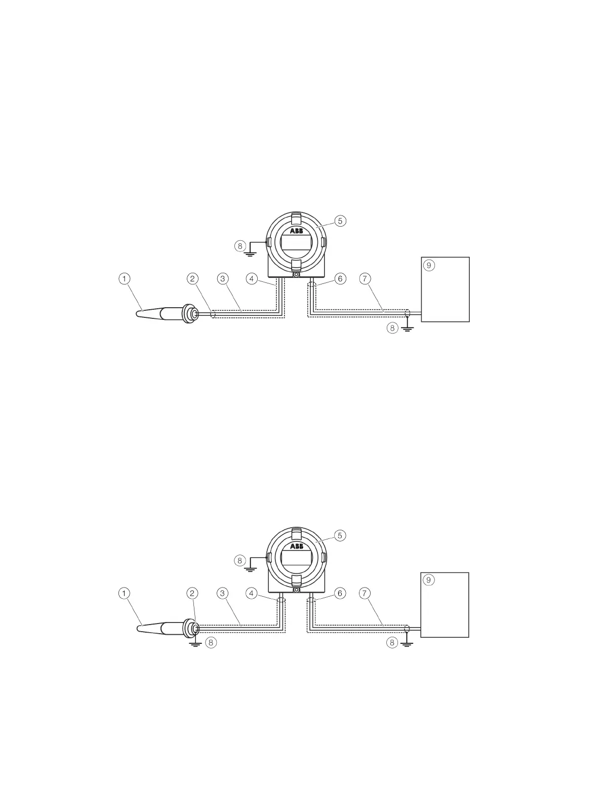
Insulated sensor measuring inset (thermocouple, mV, RTD, Ohm), transmitter housing grounded
The shielding of the sensor connection cable is grounded via the grounded transmitter housing. This shielding is insulated from the
sensor.
The shielding of the power supply cable is grounded at the supply isolator / DCS input directly This shielding is insulated from the
transmitter housing.
The shielding of the power supply cable and the shielding of sensor connection cable must not be connected to one another. Make
sure that the shielding is not connected to ground anywhere else.
Temperature sensor
Shielding insulated from sensor
Sensor connection cable
Shielding grounded via transmitter housing
Transmitter housing, grounded
Shielding insulated from transmitter housing
Supply voltage cable
Grounding point
Supply isolator / DCS input
Figure 22: The shielding of the sensor connection cable and the shielding of the power supply cable are separate and each grounded at one end
Insulated sensor measuring inset (thermocouple, mV, RTD, Ohm), transmitter housing grounded
The shielding of the sensor connection cable is grounded via the grounded pressure sensor housing. This shielding of the power
supply cable is insulated from the transmitter housing.
The shielding of the power supply cable is grounded at the supply isolator / DCS input directly This shielding is insulated from the
transmitter housing.
The shielding of the power supply cable and the shielding of sensor connection cable must not be connected to one another. Make
sure that the shielding is not connected to ground anywhere else.
Temperature sensor
Shielding grounded via sensor
Sensor connection cable
Shielding insulated from transmitter housing
Transmitter housing, grounded
Shielding insulated from transmitter housing
Supply voltage cable
Grounding point
Supply isolator / DCS input
Figure 23: The shielding of the sensor connection cable and of the supply voltage cable are separate and each grounded on one side.

 Loading...


