44 TTF300 FIELD-MOUNT TEMPERATURE TRANSMITTER | OI/TTF300-EN REV. I
10 Operation
Safety instructions
If there is a chance that safe operation is no longer possible,
take the device out of operation and secure it against
unintended startup.
Hardware settings
Devices with HART® from HW-Rev.: 02.00 (corresponds
to Software from SW-Rev.: 03.00 and higher)
HART devices from HW-Rev.: 02.00 do not have DIP switches.The
desired HART profile (HART 7 or HART 5) the write protection are
set via the operating buttons of the LCD display (optional), tools
or HART commands.
Note
Factory setting, unless explicitly ordered otherwise:
• HART 7
• Write protection OFF
Devices with PROFIBUS PA®, FOUNDATION Fieldbus®,
and HART® to HW-Rev.: 01.07
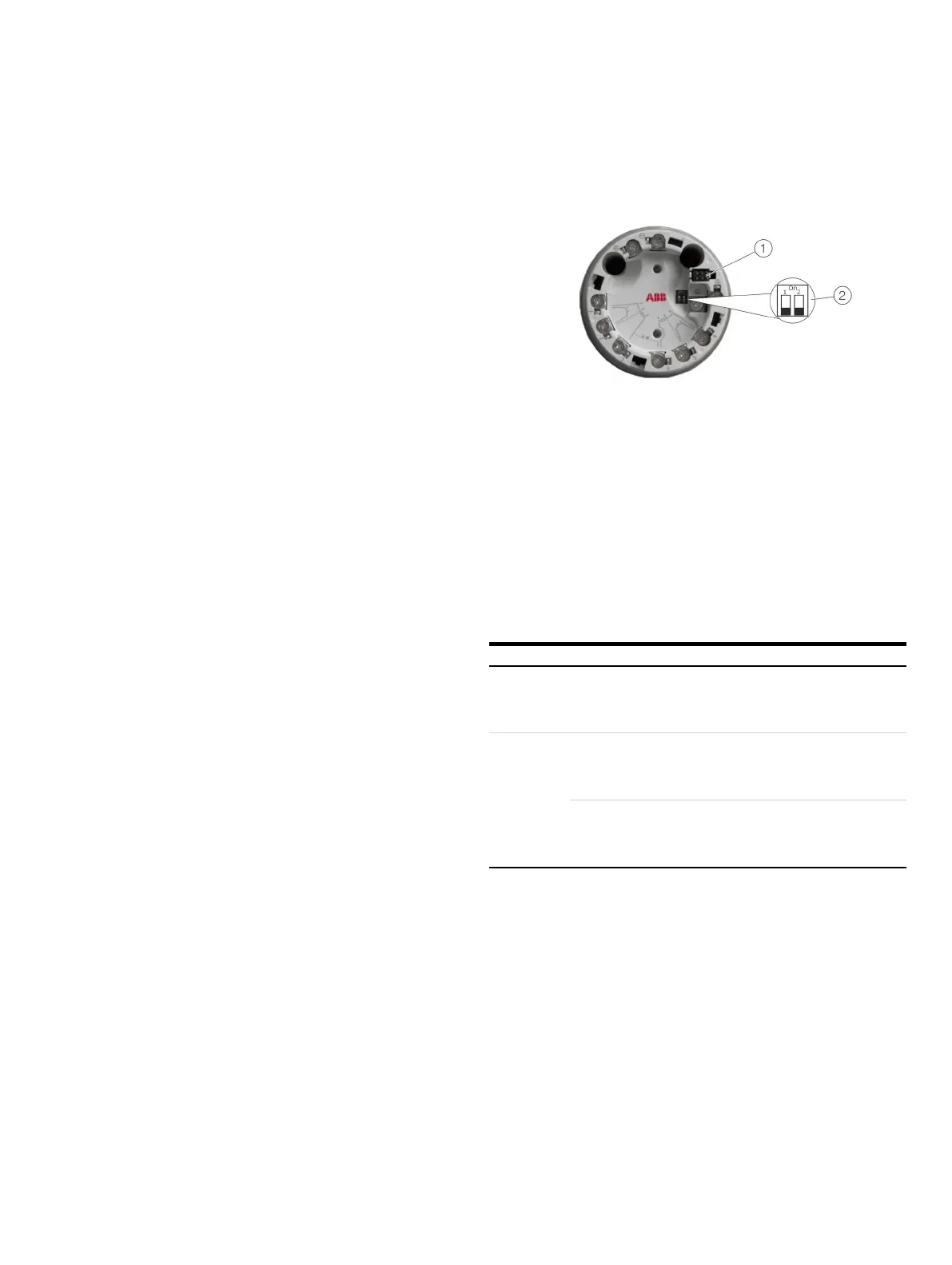
LCD indicator interface
DIP switch
Figure 34: DIP switch on the transmitter (not for HART devices from HW-Rev.: 02.00)
The transmitter has two DIP switches that can be accessed via a
hinged cover.
• Switch 1 activates the hardware write protection.
• Switch 2 supports the FOUNDATION Fieldbus
requirement for a hardware enable for simulation in
accordance with ITK.
For transmitters that support HART 7, switch 2 allows the
desired HART version to be set (HART 5 or HART 7).
: Local write protection deactivated
: Local write protection activated
Enabling the simulation (only with FOUNDATION Fieldbus)
: Simulation blocked
: Simulation enabled
Selecting the HART version (only with HART protocol)
: HART 5
: HART 7
Note (not for HART devices from HW-Rev.: 02.00)
• Factory settings: Both switches ‘OFF’. Local write protection
deactivated and HART 5, unless explicitly ordered HART 7
(HART version) or simulation locked (FOUNDATION Fieldbus).
• With PROFIBUS PA devices, Switch 2 must always be in the
‘OFF’ position.

 Loading...


