Tunable Lasers How to Modulate a Signal
146 Agilent 8163A/B, 8164A/B & 8166A/B Mainframes, Sixth Edition
Wavelength Locking
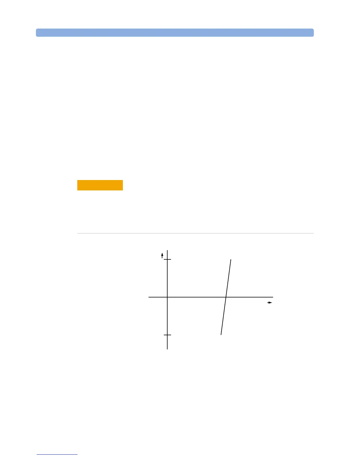
You can choose wavelength locking as the modulation source, so the the
change in output wavelength is roughly proportional to the voltage you
apply to the input BNC connector on the front panel of your Tunable Laser
module as shown in Figure 78 . This enables you to fine tune the output
wavelength within a limited wavelength range.
Wavelength locking may exhibit some hysteresis effects. The wavelength
change may differ slightly when you increase voltage from when you
decrease voltage.
If you modulate the input signal, the amplitude of the wavelength change
of the modulated optical output reduces with increasing modulation
frequency. See Appendix C of the Tunable Laser Modules User’s Guide for
more details.
Figure 78 Wavelength Locking
To enable wavelength locking:
1 Move to the Tunable Laser channel and press [Details].
2 Move to <Mod Src> and press Enter.
3 Move to <Wavel. Locking>, by using the cursor key, and press Enter. The text
λLock appears in the Tunable Laser channel.
There are two BNC connectors on the front panel of the Agilent 81480B,
Agilent 81482B, Agilent 81672B, Agilent 81680B, Agilent 81682B,
Agilent 81640B and Agilent 81642B - a BNC input connector and a BNC
output connector.
An absolute maximum of ± 6 V can be applied as an external voltage to any
BNC connector.
CAUTION
λ
V
+5 V
-5 V
 Loading...


