Return Loss Measurement Return Loss Measurement
172 Agilent 8163A/B, 8164A/B & 8166A/B Mainframes, Sixth Edition
Setup
External and Internal Sources
The Return Loss measurement setup described uses:
• An Agilent 81654A Source module, inserted as a second module in the the
same mainframe as the Return Loss module, or
• An internal source (Agilent 81611A/2A/3A/4A Return Loss modules only).
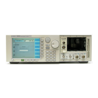
Making sure all the connectors are clean, set up the instrument as shown
in Figure 88 if you are using an External Source,
Figure 88 Return Loss Measurement Setup - External Source used
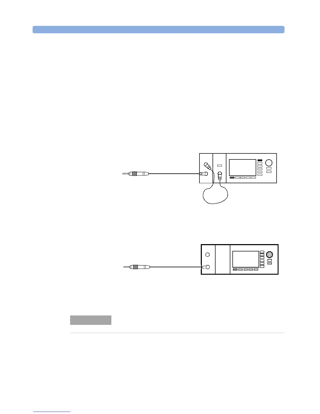
or Figure 89 if you are using an internal source
(Agilent 81611A/2A/3A/4A Return Loss modules only).
Figure 89 Return Loss Measurement Setup - Internal Source used
• If an external source is used, connect it to the Return Loss module Input.
• Attach the high return loss connector of the patchcord to the Return Loss
module Output. The high return loss connector is the connector with the
orange sleeve.
Agilent 81113PC
8161x 8163B Lightwave MultimeterLaser
Source
Agilent 81113PC
8161x
8163A/B Lightwave Multimeter
Agilent 81109AC
8161x
8163B Lightwave Multimeter
If you are using a Fabre-Perot source, you must fix its output cable to
ensure minimum cable movement.
NOTE
 Loading...


