Rockwell Automation Publication 2094-UM001J-EN-P - March 2017 157
Configure and Start the Kinetix 6000 Drive System Chapter 6
Test and Tune the Axes
These procedures assume that you have configured your Kinetix 6000 drive,
your Logix5000 Sercos interface module, and applied power to the system.
For help with using the Logix Designer application, as it applies to testing and
tuning your axes with ControlLogix, CompactLogix, or SoftLogix Sercos
modules, refer to Additional Resources on page 12
.
Test the Axes
Follow these steps to test the axes.
1. Verify the load was removed from each axis.
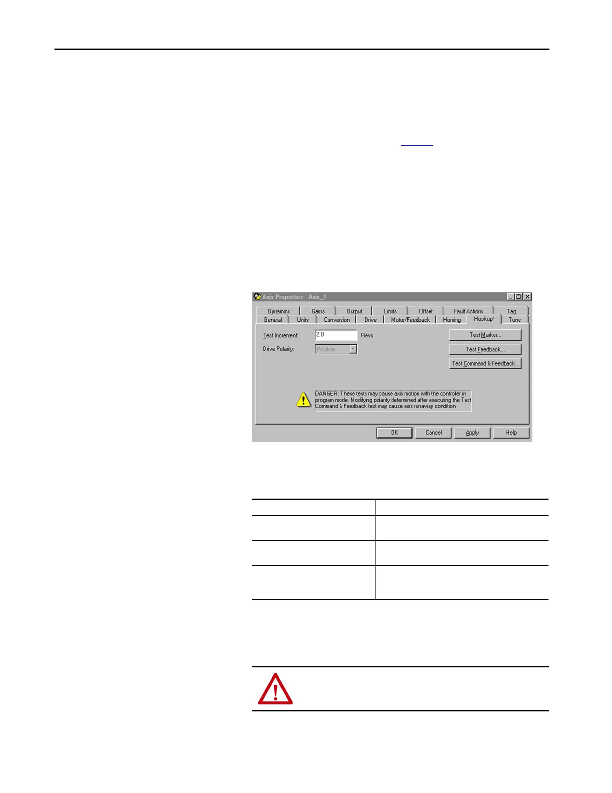
2. Right-click an axis in your Motion Group folder and choose Properties.
The Axis Properties dialog box opens.
3. Click the Hookup tab.
4. Type 2.0 as the number of revolutions for the test or another number
more appropriate for your application.
5. Apply Hardware Enable Input signal (IOD-2) for the axis you are
testing.
This Test Performs this Test
Test Marker
(1)
(1) If testing motor with brake, energize the brake circuit to release the brake prior to test.
Verifies marker detection capability as you rotate the motor
shaft.
Test Feedback
(1)
Verifies feedback connections are wired correctly as you
rotate the motor shaft. Also, lets you define polarity.
Test Command & Feedback
Verifies motor power and feedback connections are wired
correctly as you command the motor to rotate. Also, lets you
define polarity.
ATTENTION: To avoid personal injury or damage to equipment,
apply 24V ENABLE signal (IOD-2) only to the axis you are testing.
 Loading...


