Rockwell Automation Publication 2094-UM001J-EN-P - March 2017 67
Connector Data and Feature Descriptions Chapter 4
Control Signal Specifications
This section provides a description of the Kinetix 6000 drive
I/O (IOD), communication, contactor enable (CED), brake (BC), and
control power (CPD) connectors.
Digital Inputs
Two fast registration inputs and four other inputs are available for the machine
interface on the IAM module and AM module. Each IAM and AM module
supplies 24V DC @ 250 mA for the purpose of registration, home, enable,
over-travel positive, and over-travel negative inputs. These are sinking inputs
that require a sourcing device. A 24V DC power and common connection is
provided for each input.
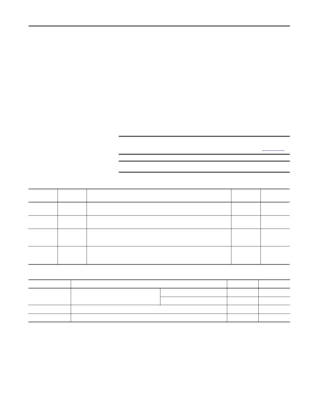
Table 37 - Understanding Digital Inputs
Table 38 - Digital Input Specifications
IMPORTANT To improve registration input EMC performance, refer to the System Design
for Control of Electrical Noise Reference Manual, publication GMC-RM001
.
IMPORTANT Over-travel limit input devices must be normally closed.
IOD Pin Signal Description Capture Time
Edge/Level
Sensitive
IOD-2 ENABLE
Optically isolated, single-ended active high signal. Current loading is nominally 10 mA. A 24V DC
input is applied to this terminal to enable each axis.
20 ms Level
IOD-5 HOME
Optically isolated, single-ended active high signal. Current loading is nominally 10 mA. Home
switch (normally open contact) inputs for each axis require 24V DC (nominal).
20 ms Level
IOD-14
IOD-17
REG1
REG2
Fast registration inputs are required to inform the motor interface to capture the positional
information with less than 3 µs uncertainty. Optically isolated, single-ended active high signal.
Current loading is nominally 10 mA. A 24V DC input is applied to this terminal to enable each axis.
500 ns Edge
IOD-8
IOD-11
OT+
OT-
Overtravel detection is available as an optically isolated, single-ended active high signal. Current
loading is nominally 10 mA per input. The pos/neg limit switch (normally closed contact) inputs
for each axis require 24V DC (nominal).
30 ms Level
Parameter Description Min Max
On-state voltage
Voltage applied to the input, with respect to IOCOM, to
guarantee an on-state.
ENABLE, HOME, and OT+/OT- 10.8V 26.4V
REG1 and REG2 21.6V 26.4V
On-state current Current flow to guarantee an on-state. 3.0 mA 10.0 mA
Off-state voltage Voltage applied to the input, with respect to IOCOM, to guarantee an off-state. -1.0V 3.0V
 Loading...


