Rockwell Automation Publication 2094-UM001J-EN-P - March 2017 61
Connector Data and Feature Descriptions Chapter 4
I/O Connector Pinout
Table 25 - IAM/AM I/O 26-pin (IOD) Connector
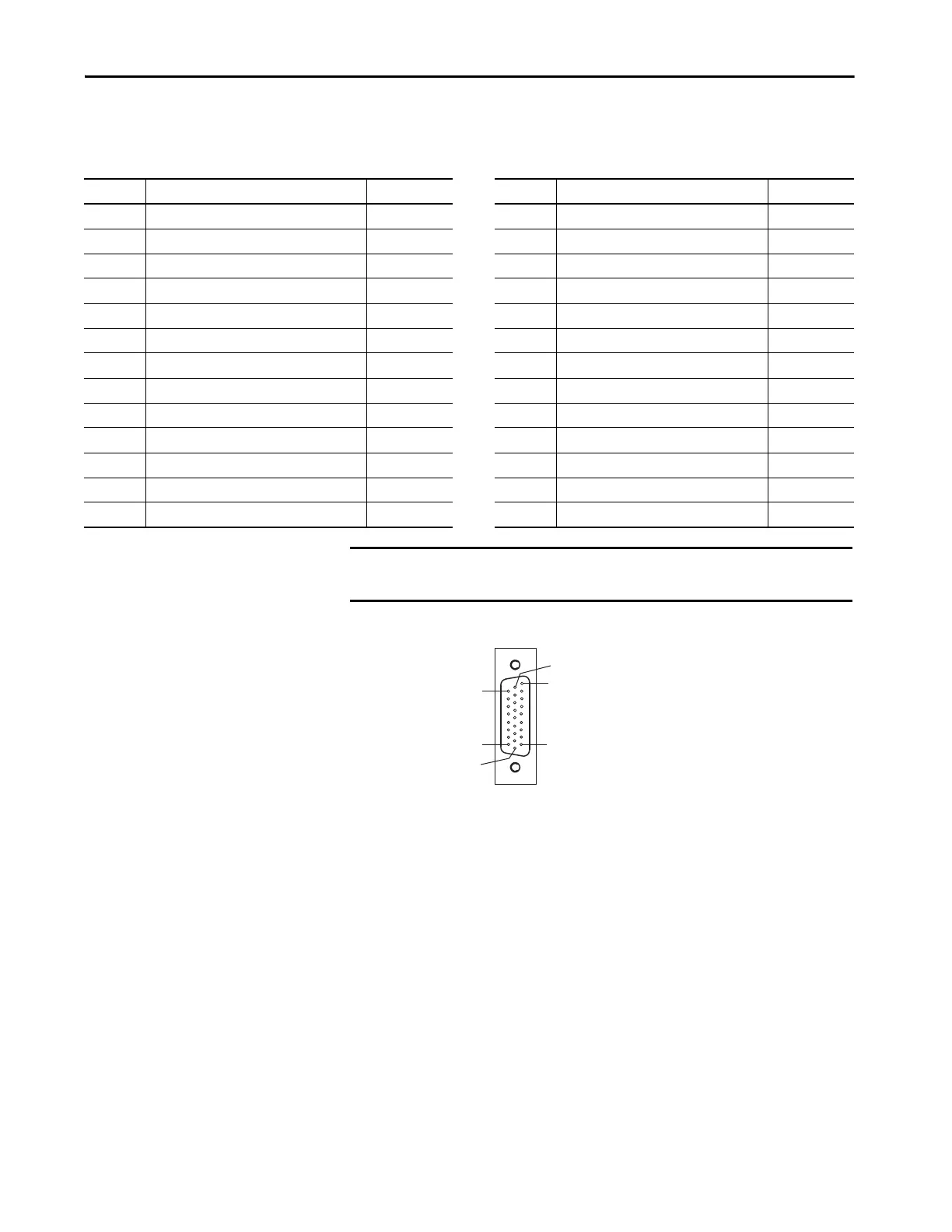
Figure 26 - Pin Orientation for 26-pin I/O (IOD) Connector
IOD Pin Description Signal IOD Pin Description Signal
1 Hardware enable 24V DC power supply +24V_PWR 14 High speed registration 1 input REG1
2 Hardware enable input ENABLE 15 Common for registration REG_COM
3 Common +24V_COM 16 24V registration power REG_24V
4 Home switch 24V DC power supply +24V_PWR 17 High speed registration 2 input REG2
5 Home switch input HOME 18 Common for registration REG_COM
6 Common +24V_COM 19 Reserved –
7 Positive overtravel 24V DC power supply +24V_PWR 20 Reserved –
8 Positive overtravel limit switch input OT+ 21 Reserved –
9 Common +24V_COM 22 Reserved –
10 Negative overtravel 24V DC power supply +24V_PWR 23 Analog output 0 DAC0
11 Negative overtravel limit switch input OT- 24 Analog output common DAC_COM
12 Common +24V_COM 25 Analog output 1 DAC1
13 24V registration power REG_24V 26 Analog output common DAC_COM
IMPORTANT Signals +24V_PWR and +24V_COM are a 24V DC source you can use only
for the inputs listed above.
Pin 18
Pin 26
Pin 1
Pin 9
Pin 10
Pin 19
 Loading...


