Rockwell Automation Publication 2094-UM001J-EN-P - March 2017 159
Configure and Start the Kinetix 6000 Drive System Chapter 6
Tune the Axes
The load observer feature (available with drive firmware revision 1.124 or
later) can provide good performance without having to tune your axis. Using
load observer with auto-tuned gains can maximize system performance. Refer
to Appendix D beginning on page 237
for more load observer information.
Follow these steps to tune the axes.
1. Verify the load is still removed from the axis being tuned.
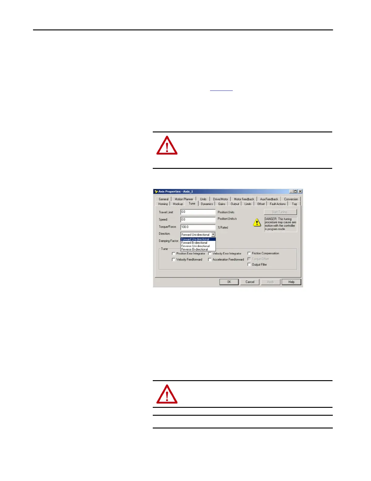
2. Click the Tune tab.
3. Type values for Travel Limit and Speed.
In this example, Travel Limit = 5 and Speed = 10. The actual value of
programmed units depend on your application.
4. From the Direction pull-down menu, choose a setting.
Forward Uni-directional is default.
5. Check Tune boxes as appropriate for your application.
6. Apply Hardware Enable Input signal (IOD-2) for the axis you are
tuning.
ATTENTION: To reduce the possibility of unpredictable motor
response, tune your motor with the load removed first, then re-
attach the load and perform the tuning procedure again to provide
an accurate operational response.
ATTENTION: To avoid personal injury or damage to equipment,
apply 24V ENABLE signal (IOD-2) only to the axis you are tuning.
IMPORTANT Hardware Enable input for IDM units is on the IPIM module.
 Loading...


