Rockwell Automation Publication 2080-UM001B-EN-E - November 2011 23
Wire Your Controller Chapter 4
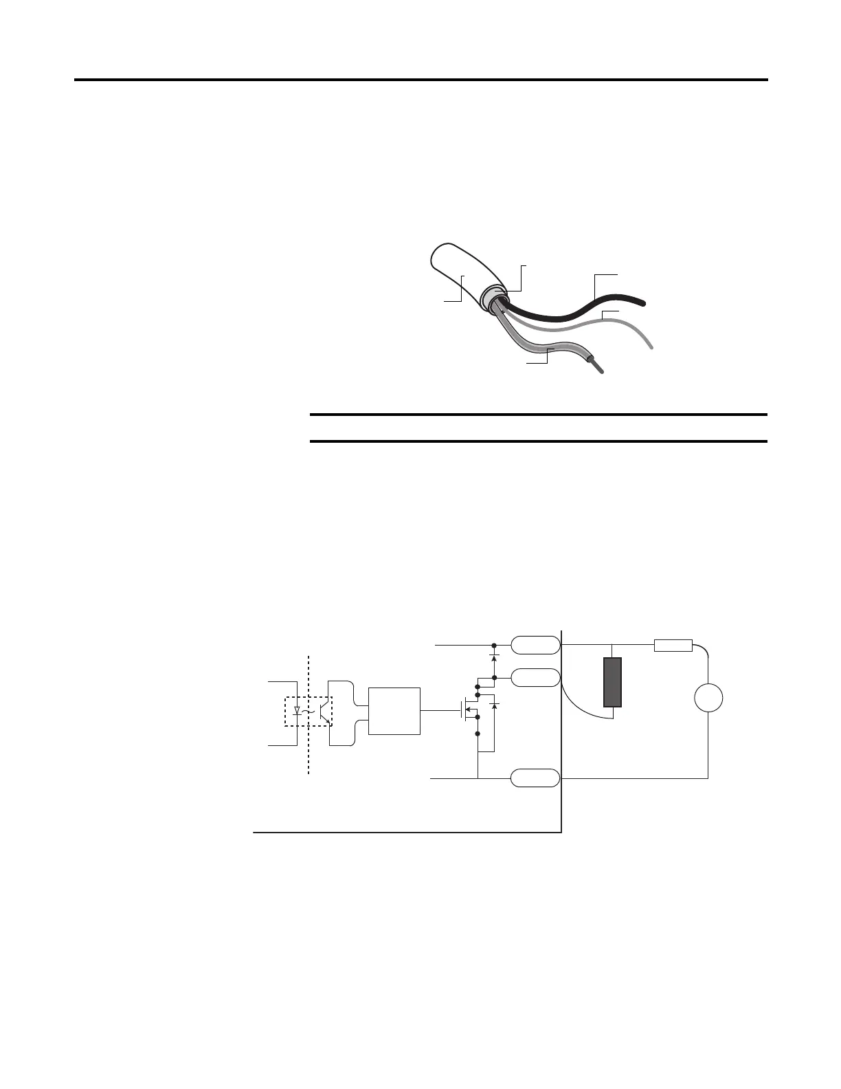
Ground Your Analog Cable
Use shielded communication cable (Belden #8761). The Belden cable has two
signal wires (black and clear), one drain wire, and a foil shield. The drain wire and
foil shield must be grounded at one end of the cable.
Wiring Examples
Examples of sink/source, input/output wiring are shown below.
Ground the drain wire and foil shield at field side.
Foil shield
Black wire
Drain wire
Clear wire
Insulation
44531
Sink output wiring example
D
DC COM
OUT
+V DC
S
G
+
–
24V Supply
Logic side
User side
Micro800 QVB controller
Load
Fuse
 Loading...


