Publication 1762-RM001C-EN-P
Using High-Speed Outputs 6-19
instruction is actually being executed by a parallel system, the status bits
and other information are updated each time the PWM instruction is
scanned while it is running. This provides the control program access to
PWM status while it is running.
Pulse Width Modulation
(PWM) Function File
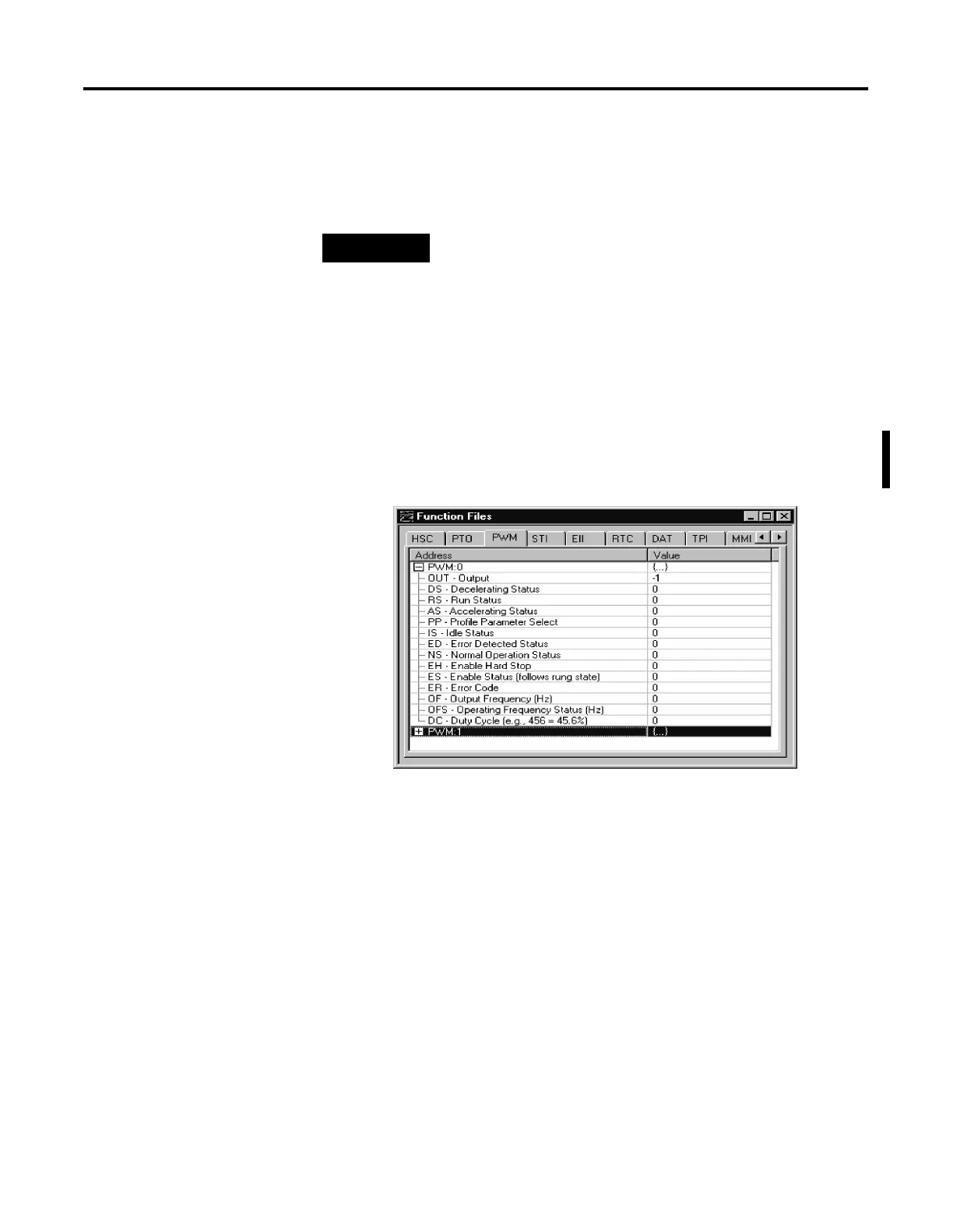
Within the PWM function file are two PWM elements. Each element can
be set to control either output 2 (O0:0/2 on 1762-L24BXB, 1762-L40BXB,
and 1764-28BXB) or output 3 (O0:0/3 on 1764-28BXB only). Function file
element PWM:0 is shown below.
NOTE
PWM status is only as fresh as the scan time of the
controller. Worst case latency is the maximum scan of the
controller. This condition can be minimized by placing a
PWM instruction in the STI (selectable timed interrupt)
file, or by adding PWM instructions to your program to
increase how often a PWM instruction is scanned.

 Loading...


