Publication 1762-RM001C-EN-P
I/O Configuration 1-15
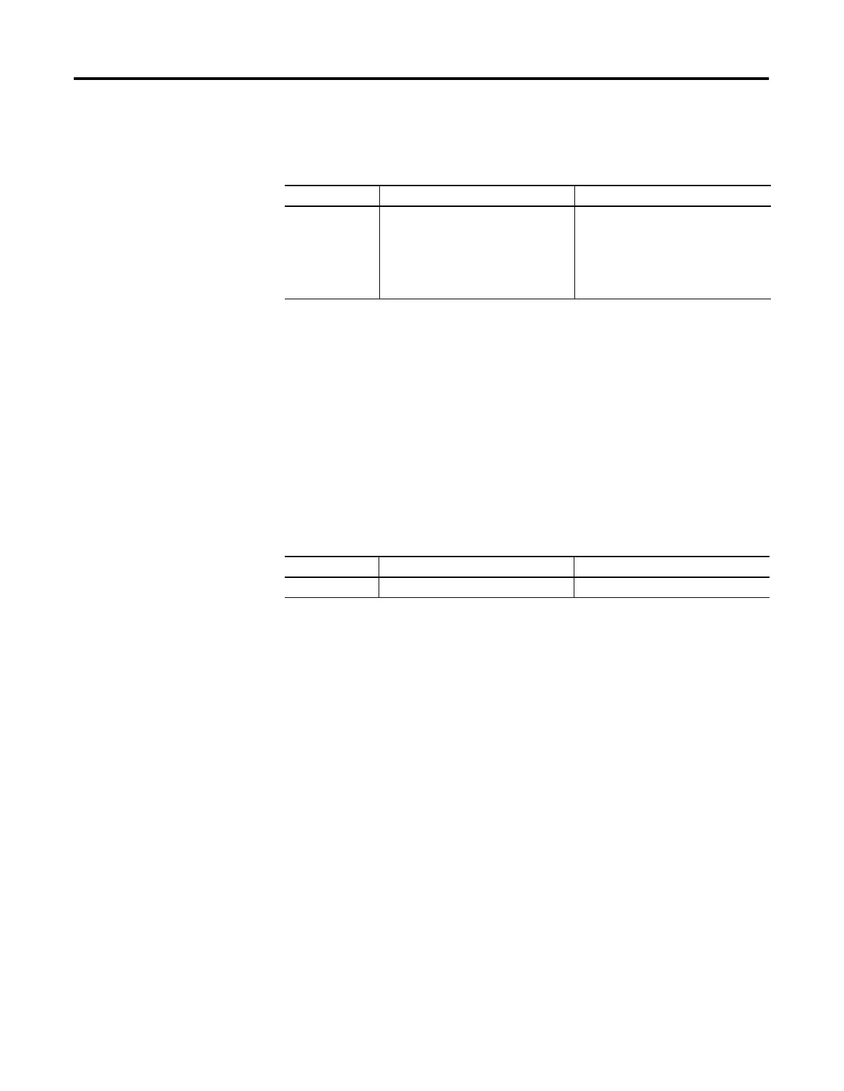
The input groups are pre-arranged. Simply select the filter time you
require for each input group. You can apply a unique input filter setting
to each of the input groups:
The minimum and maximum response times associated with each input
filter setting can be found in your controller’s User Manual.
Latching Inputs
The MicroLogix 1200 and 1500 controllers provide the ability to
individually configure inputs to be latching inputs (sometimes referred to
as pulse catching inputs). A latching input is an input that captures a very
fast pulse and holds it for a single controller scan. The pulse width that
can be captured is dependent upon the input filtering selected for that
input.
The following inputs can be configured as latching inputs:
You enable this feature with RSLogix 500 programming software. With an
open project:
1. Open the “Controller” folder.
2. Open the “I/O Configuration” folder.
3. Open slot 0 (controller).
4. Select the “embedded I/O configuration” tab.
5. Select the mask bits for the inputs that you want to operate as latching
inputs.
6. Select the state for the latching inputs. The controller can detect both
“on” (rising edge) and “off” (falling edge) pulses, depending upon the
configuration selected in the programming software.
The following information is provided for a controller looking for an “on”
pulse. When an external signal is detected “on”, the controller “latches”
this event. In general, at the next input scan following this event, the
input image point is turned “on” and remains “on” for the next controller
scan. It is then set to “off” at the next input scan. The following figures
help demonstrate this.
Controller MicroLogix 1200 MicroLogix 1500
Input Groups
•
0 and 1
•
2 and 3
•
4 and above
•
0 and 1
•
2 and 3
•
4 and 5
•
6 and 7
•
8 and above
Controller MicroLogix 1200 MicroLogix 1500
DC Inputs 0 through 3 0 through 7

 Loading...


