Publication 1762-RM001C-EN-P
19-2 Process Control Instruction
The PID Equation
The PID instruction uses the following algorithm:
Standard equation with dependent gains:
Standard Gains constants are:
The derivative term (rate) provides smoothing by means of a low-pass
filter. The cut-off frequency of the filter is 16 times greater than the corner
frequency of the derivative term.
PD Data File
The PID instruction implemented by the MicroLogix 1200 and 1500
controllers is virtually identical in function to the PID implementation
used by the Allen-Bradley SLC 5/03 and higher processors. Minor
differences primarily involve enhancements to terminology. The major
difference is that the PID instruction now has its own data file. In the SLC
family of processors, the PID instruction operated as a block of registers
within an integer file. The Micrologix 1200 and 1500 PID instruction
utilizes a PD data file.
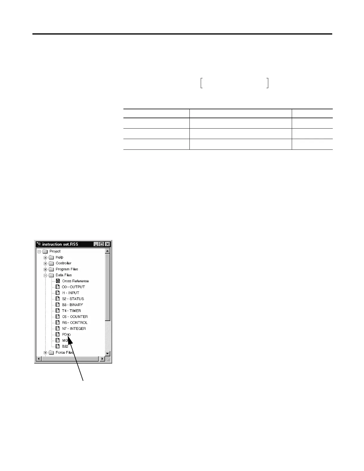
You can create a PD data file by creating a new data file and classifying it
as a PD file type. RSLogix automatically creates a new PD file or a PD
sub-element whenever a PID instruction is programmed on a rung. The
PD file then appears in the list of Data Files as shown in the illustration.
Each PD data file has a maximum of 255 elements and each PID
instruction requires a unique PD element. Each PD element is composed
of 20 sub-elements, which include bit, integer and long integer data. All of
the examples in this chapter use PD file 10 sub-element 0.
Term Range (Low to High) Reference
Controller Gain K
C
0.01 to 327.67 (dimensionless)
(1)
(1) Applies to MicroLogix 1200 and 1500 PID range when Reset and Gain Range (RG) bit is set to 1. For more information
on reset and gain, see PLC 5 Gain Range (RG) on pa ge19-13.
Proportional
Reset Term 1/T
I
327.67 to 0.01 (minutes per repeat)
(1)
Integral
Rate Term T
D
0.01 to 327.67 (minutes)
(1)
Derivative
Output K
C
E()
1
T
I
-----
E()td
∫
T
D
dPV()
dt
--------- ------
⋅++ bias+=
PD file created by
RSLogix 500.

 Loading...


