Publication 1762-RM001C-EN-P
7-6 Relay-Type (Bit) Instructions
The ONS Storage Bit is the bit address that remembers the rung state from
the previous scan. This bit is used to remember the false-to-true rung
transition.
Addressing Modes and File Types can be used as shown in the following
table:
OSR - One Shot Rising
OSF - One Shot Falling
Instruction Type: output
Table 7.9 ONS Instruction Operation
Rung Transition Storage Bit Rung State after Execution
false-to-true (one scan) storage bit is set true
true-to-true storage bit remains set false
true-to-false, false-to-false storage bit is cleared false
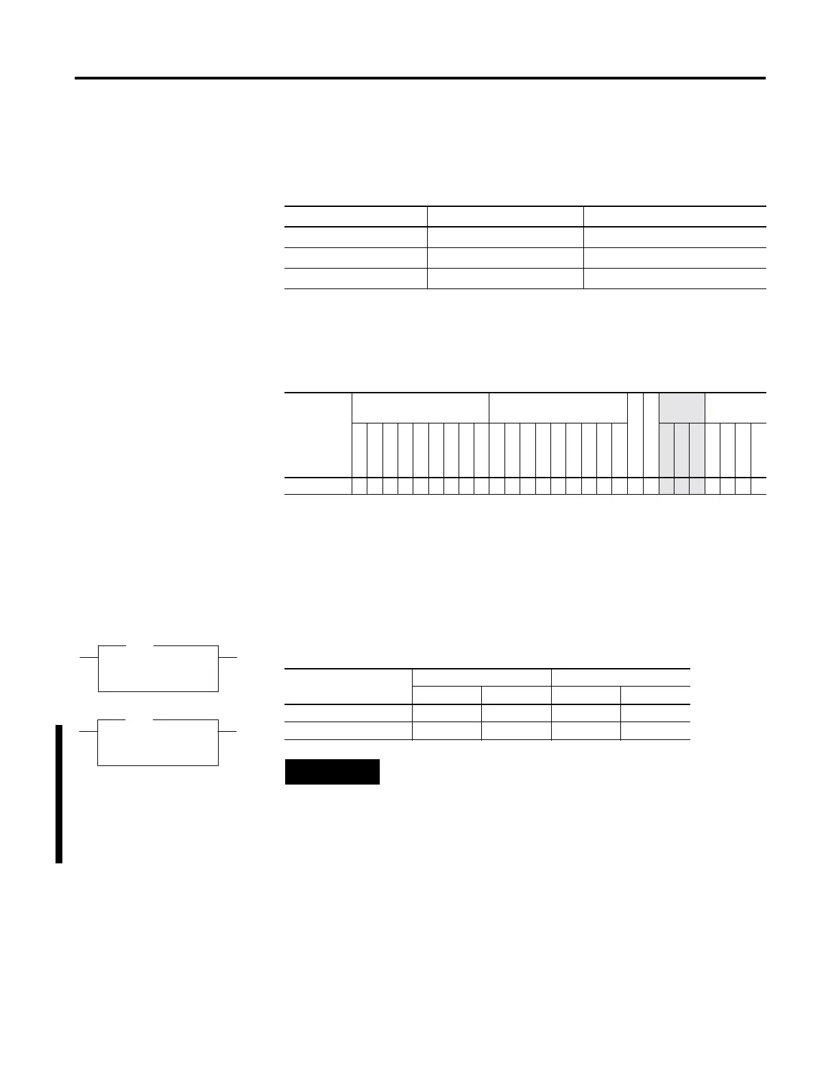
Table 7.10 ONS Instruction Valid Addressing Modes and File Types
For definitions of the terms used in this table see Using the Instruction Descriptions on page4-2.
Parameter
Data Files Function Files
CS - Comms
IOS - I/O
Address
Mode
Address
Level
O
I
S
B
T, C, R
N
ST
L
MG, PD
RTC
HSC
PTO, PWM
STI
EII
BHI
MMI
DAT
TPI
Immediate
Direct
Indirect
Bit
Word
Long Word
Element
Storage Bit •• • •
OSR
One Shot Rising
Storage Bit B3:0/0
Output Bit B3:0/1
OSR
OSF
One Shot Falling
Storage Bit B3:0/0
Output Bit B3:0/1
OSF
Table 7.11 Execution Time for the OSR and OSF Instructions
Controller OSR - When Rung Is: OSF - When Rung Is:
True False True False
MicroLogix 1200 3.4 µs 3.0 µs 2.8 µs 3.7 µs
MicroLogix 1500 3.2 µs 2.8 µs 2.7 µs 3.4 µs
NOTE
The OSR instruction for the MicroLogix 1200 and 1500
does not provide the same functionality as the OSR
instruction for the MicroLogix 1000 and SLC 500
controllers. For the same functionality as the OSR
instruction for the MicroLogix 1000 and SLC 500
controllers, use the ONS instruction.

 Loading...


