Publication 1762-RM001C-EN-P
Function Files 3-5
Trim Pot Information
Function File
The composition of the Trim Pot Information (TPI) Function File is
described below.
The data resident in TPI:0.POT0 represents the position of trim pot 0. The
data resident in TPI:0.POT1 corresponds to the position of trim pot 1. The
valid data range for both is from 0 (counterclockwise) to 250 (clockwise).
Error Conditions
If the controller detects a problem with either trim pot, the last values
read remain in the data location, and an error code is put in the error
code byte of the TPI file for whichever trim pot had the problem. Once
the controller can access the trim pot hardware, the error code is cleared.
The error codes are described in the table below.
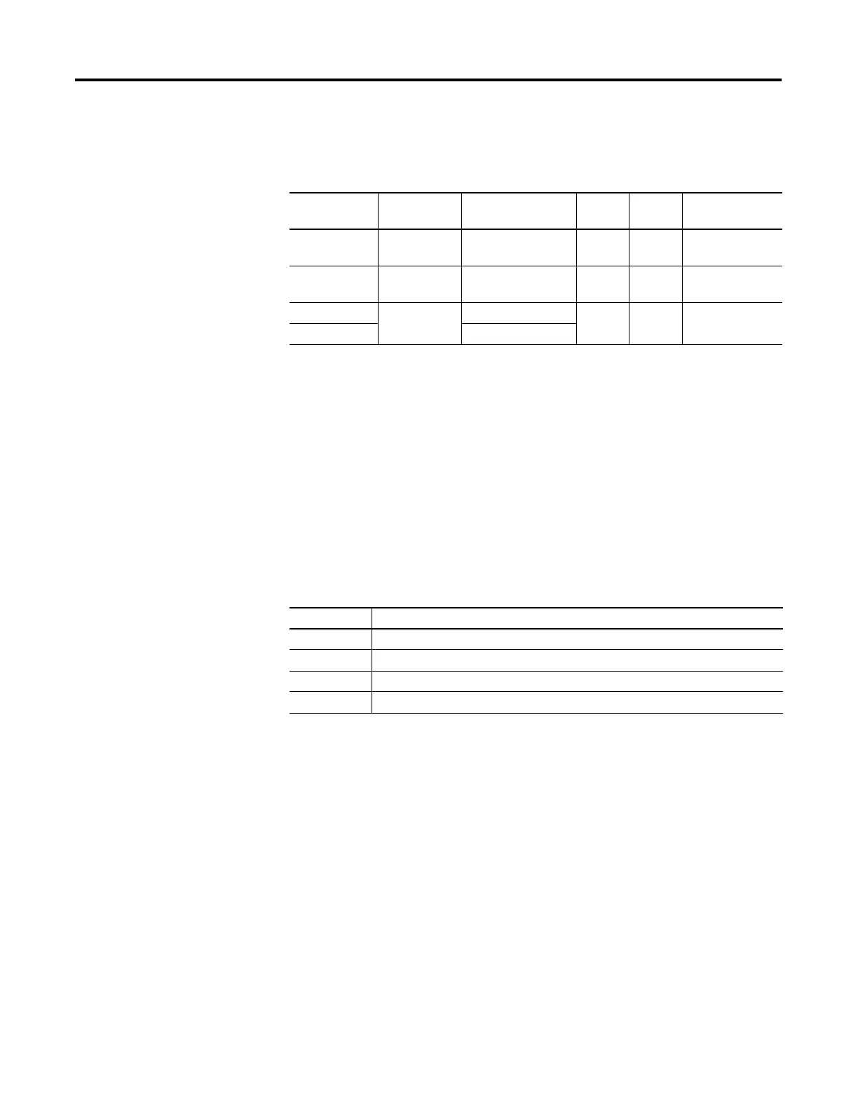
Table 3.5 Trim Pot Function File
Data Address Data Format Range Type User Program
Access
TPD Data O TPI:0.POT0 Word
(16-bit integer)
0 - 250 Status Read Only
TPD Data 1 TPI:0.POT1 Word
(16-bit integer)
0 - 250 Status Read Only
TP0 Error Code TPI:0.ER Word (bits 0 to 7) 0 - 3 Status Read Only
TP1 Error Code Word (bits 8 to 15)
Table 3.6 Trim Pot Error Codes
Error Code Description
0 Trim pot data is valid.
1 Trim pot subsystem detected, but data is invalid.
2 Trim pot subsystem did not initialize.
3 Trim pot subsystem failure.

 Loading...


