Publication 1762-RM001C-EN-P
5-26 Using the High-Speed Counter
HSL - High-Speed
Counter Load
Instruction Type: output
The HSL (High-Speed Load) instruction allows the high and low presets,
and high and low output source to be applied to a high-speed counter.
These parameters are described below:
•
Counter Number - Specifies which high-speed counter is being used;
0 = HSC0 and 1 = HSC1 (MicroLogix 1500 only).
•
High Preset - Specifies the value in the high preset register. The data
ranges for the high preset are -32786 to 32767 (word) and
-2,147,483,648 to 2,147,483,647 (long word).
•
Low Preset - Specifies the value in the low preset register. The data
ranges for the low preset are -32786 to 32767 (word) and
-2,147,483,648 to 2,147,483,647 (long word).
•
Output High Source - Specifies the value in the output high register.
The data range for the output high source is from 0 to 65,535.
•
Output Low Source - Specifies the value in the output low register.
The data range for the output low source is from 0 to 65,535.
Valid Addressing Modes and File Types are shown below:
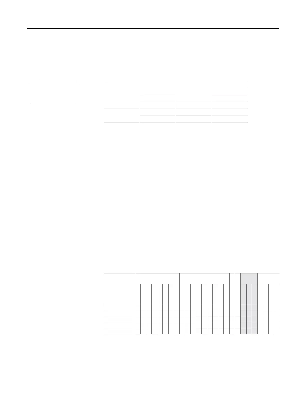
HSL
High Speed Counter Load
HSC Number HSC0
High Preset N7:0
Low Preset N7:1
Output High Source N7:2
Output Low Source N7:3
HSL
Controller Data Size Execution Time When Rung Is:
True False
MicroLogix 1200 word 46.7
µ
s0.0
µ
s
long word 47.3
µ
s0.0
µ
s
MicroLogix 1500 word 39.7
µ
s0.0
µ
s
long word 40.3
µ
s0.0
µ
s
Table 5.13 HSL Instruction Valid Addressing Modes and File Types
For definitions of the terms used in this table see Using the Instruction Descriptions on page 4-2.
Parameter
Data Files Function Files
CSF - Comms
IOS - I/O
Address
Mode
Address
Level
O
I
S
B
T, C, R
N
L
MG, PD
RTC
HSC
PTO, PWM
STI
EII
BHI
MMI
DAT
TPI
Immediate
Direct
Indirect
Bit
Word
Long Word
Element
Counter Number •
High Preset •• •••• • • •••
Low Preset •• ••••
• • •••
Output High Source •• ••••
• • •••
Output Low Source •• ••••
• • •••

 Loading...


