Publication 1762-RM001C-EN-P
21-28 Communications Instructions
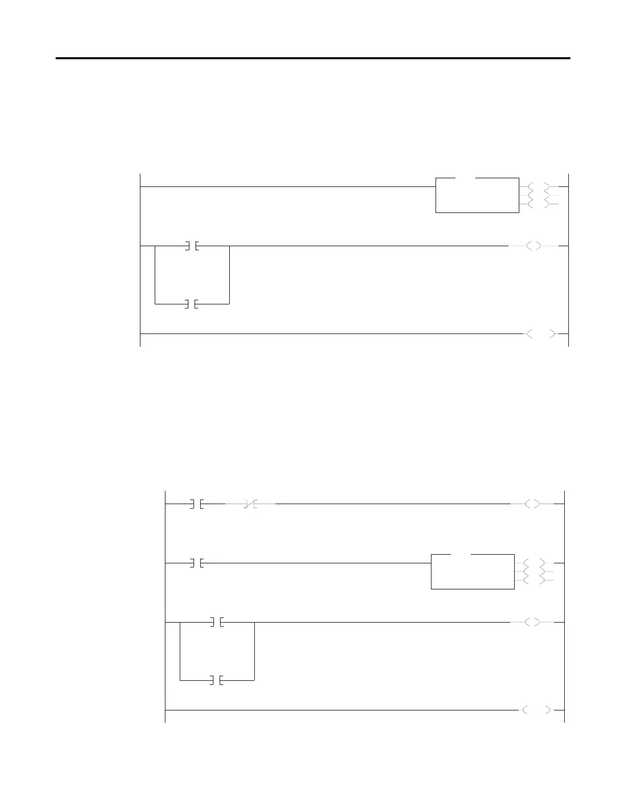
MSG Instruction Ladder
Logic
Enabling the MSG Instruction for Continuous Operation
The message instruction is enabled during the initial processor program
scan and each time the message completes. For example, when the DN or
ER bit is set.
Enabling the MSG Instruction Via User Supplied Input
This is an example of controlling when the message instruction operates.
Input I:1/0 could be any user-supplied bit to control when messages are
sent. Whenever I:1/0 is set and message MG11:0 is not enabled, the
message instruction on rung 0001 is enabled.
0000
EN
DN
ER
MSG
Read/Write Message
MSG File MG11:0
Setup Screen
MSG
0001
MG11:0
DN
MG11:0
ER
U
MG11:0
EN
0002
END
Message Done Bit
Message Error Bit
Message Enable Bit
0000
I:1
0
MG11:0
EN
L
B3:0
0
0001
B3:0
0
EN
DN
ER
MSG
Read/Write Message
MSG File MG11:0
Setup Screen
MSG
0002
MG11:0
DN
MG11:0
ER
U
B3:0
0
0003
END
Message Done Bit
Message Error Bit
The message instruction is enabled with each
false-to-true transition of bit B3:0/0
User Supplied
Input
Message
Enable Bit

 Loading...


