Publication 1762-RM001C-EN-P
20-6 ASCII Instructions
Control Data File
File Description
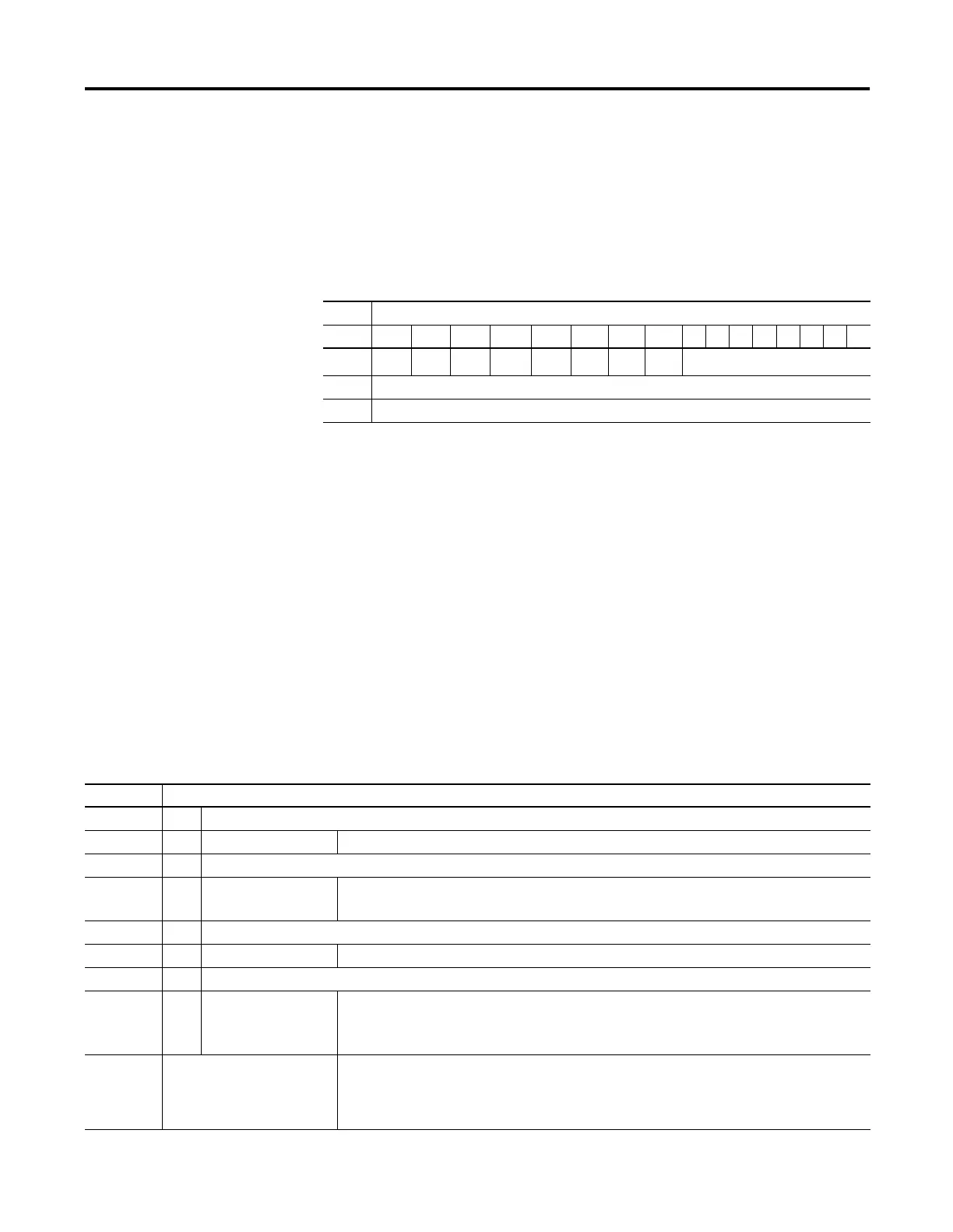
The control data element is used by ASCII instructions to store control
information required to operate the instruction. The control data element
for ASCII instructions includes status and control bits, an error code byte,
and two character words as shown below:
Addressing Control Files
The addressing scheme for the control data file is shown below.
Table 20.2 ASCII Instructions Control Data File Elements
Control Element
Word 15 14 13 12 11 10 09 08 07 06 05 04 03 02 01 00
0
EN
(1)
(1) EN = Enable Bit - indicates that an instruction is enabled due to a false-to-true transition. This bit remains set until the
instruction completes execution or generates an error.
EU
(2)
(2) EU = Queue Bit - when set, indicates that an ASCII instruction was placed in the ASCII queue. This action is delayed if
the queue is already filled.
DN
(3)
(3) DN = Asynchronous Done Bit - is set when an instruction successfully completes its operation.
EM
(4)
(4) EM = Synchronous Done Bit - not used
ER
(5)
(5) ER = Error Bit - when set, indicates that an error occurred while executing the instruction.
UL
(6)
(6) UL = Unload Bit - when this bit is set by the user, the instruction does not execute. If the instruction is already
executing, operation ceases. If this bit is set while an instruction is executing, any data already processed is sent to
the destination and any remaining data is not processed. Setting this bit will not cause instructions to be removed
from the ASCII queue. This bit is only examined when the instruction is ready to start executing.
RN
(7)
(7) RN = Running Bit - when set, indicates that the queued instruction is executing.
FD
(8)
(8) FD = Found Bit - when set, indicates that the instruction has found the end-of-line or termination character in the
buffer. (only used by the ABL and ACB instructions)
Error Code Byte
1 Number of characters specified to be sent or received (LEN)
2 Number of characters actually sent or received (POS)
Format Explanation
R Control file
R:e.s/b f File number The valid file number range is from 3 to 255.
: Element delimiter
e Element number The valid element number range is from 0 to 255.
Each element is 3 words in length as shown in Table 20.2.
. Subelement delimiter
s Subelement number The valid subelement number range is from 0 to 2. You can also specify .LEN or .POS.
/ Bit delimiter
b Bit number The valid bit number range is from 0 to 15.
The bit number is the bit location within the string file element.
Bit level addressing is not available for words 1 and 2 of the control element.
Examples: R6:2
R6:2.0/13
R18:1.LEN
R18:1.POS
Element 2, control file 6
Bit 13 in sub-element 0 of element 2, control file 6
Specified string length of element 1, control file 1 8
Actual string length of element 1, control file 18

 Loading...


