Publication 1762-RM001C-EN-P
20-8 ASCII Instructions
Addressing Modes and File Types can be used as shown below:
Instruction Operation
When Clear Receive Buffer and Clear Transmit Buffer are both set to Yes,
all Receive and Transmit instructions (ARL, ARD, AWA, and AWT) are
removed from the ASCII queue.
When instructions are removed from the ASCII queue, the following bits
are set: ER = 1, RN = 0, EU = 0, and ERR = 0x0E.
AIC - ASCII Integer to
String
Instruction Type: output
The AIC instruction converts an integer or long word value (source) to an
ASCII string (destination). The source can be a constant or an address.
The source data range is from -2,147,483,648 to 2,147,483,647.
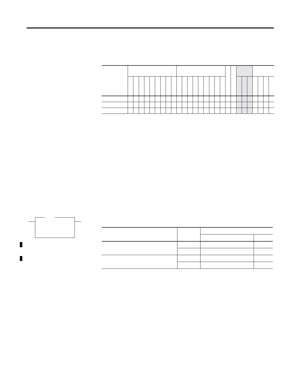
Table 20.4 ACL Instruction Valid Addressing Modes and File Types
For definitions of the terms used in this table see Using the Instruction Descriptions on page4-2.
Parameter
Data Files
(1)
(1) The Control data file is the only valid file type for the Control Element.
Function Files
CS - Comms
IOS - I/O
Address
Mode
Address
Level
O
I
S
B
T, C, R
N
ST
L
MG, PD
RTC
HSC
PTO, PWM
STI
EII
BHI
MMI
DAT
TPI
Immediate
Direct
Indirect
Bit
Word
Long Word
Element
Channel • •
Receive Buffer
• •
Transmit Buffer
• •
AIC
Integer to String
Source N7:0
Dest ST14:1
AIC
Table 20.5 Execution Time for the AIC Instruction
Controller Data Size When Instruction Is:
True False
MicroLogix 1200 word 29.3
µ
s + 5.2
µ
s/character 0.0
µ
s
long word 82.0
µ
s0.0
µ
s
MicroLogix 1500 Series B, FRN 4 or later word 25
µ
s + 4.3
µ
s/character 0.0
µ
s
long word 68.7
µ
s0.0
µ
s

 Loading...


