Publication 1762-RM001C-EN-P
6-20 Using High-Speed Outputs
Pulse Width Modulated
Function File Elements
Summary
The variables within each PWM element, along with what type of
behavior and access the control program has to those variables, are listed
individually below.
PWM Output (OUT)
The PWM OUT (Output) variable defines the physical output that the
PWM instruction controls. This variable is set within the function file
folder when the control program is written and cannot be set by the user
program. The outputs are defined as O0:0/2 or O0:0/3 as listed below:
•
O0:0.0/2: PWM modulates output 2 of the embedded outputs
(1762-L24BXB, 1762-L40BXB, and 1764-28BXB)
•
O0:0.0/3: PWM modulates output 3 of the embedded outputs
(1764-28BXB only)
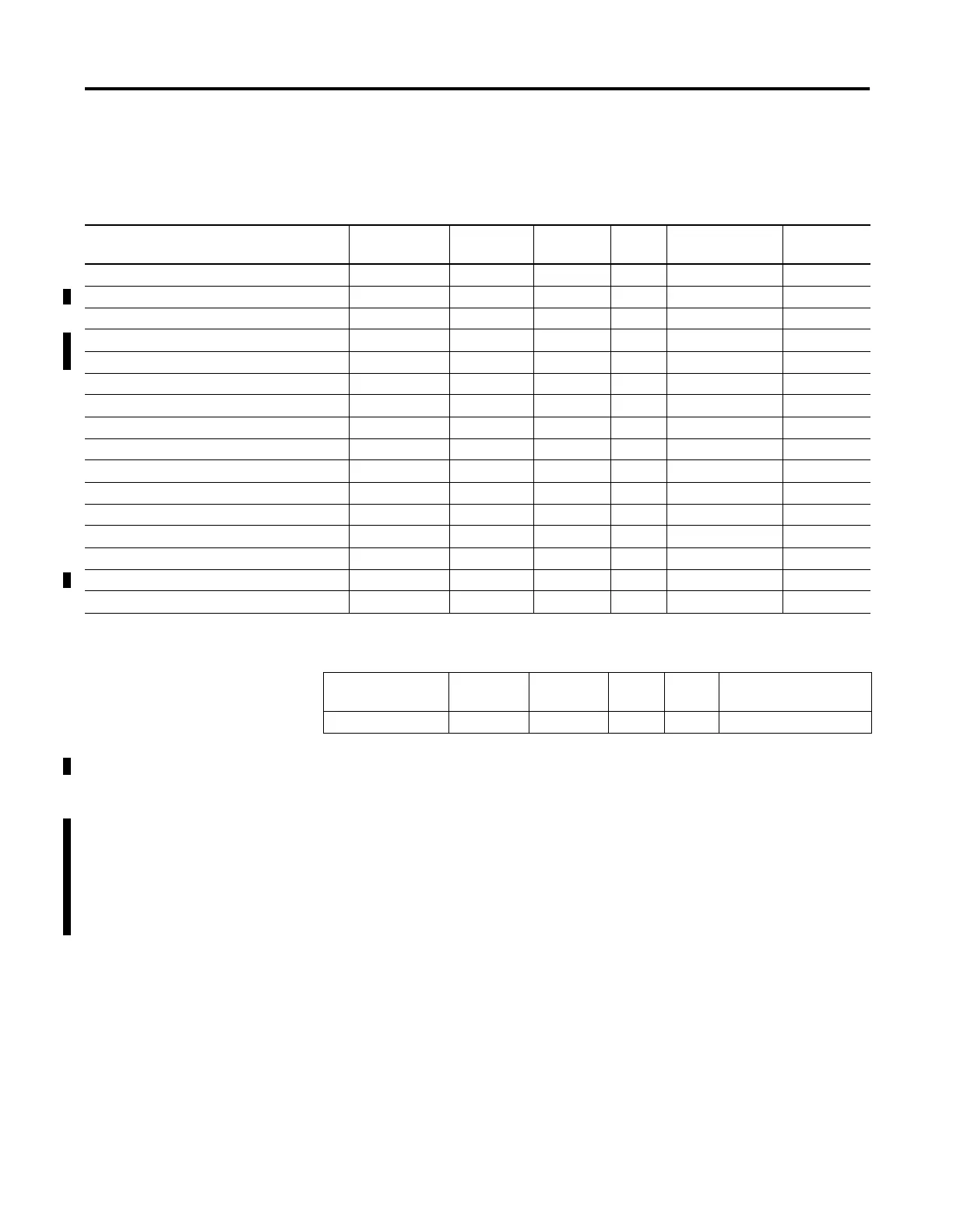
Element Description Address Data Format Range Type User Program
Access
For More
Information
OUT - PWM Output PWM:0.OUT word (INT) 2 or 3 status read only 6-20
DS - Decelerating Status PWM:0/DS bit 0 or 1 status read only 6-21
RS - PWM Run Status PWM:0/RS bit 0 or 1 status read only 6-21
AS - Accelerating Status PWM:0/AS bit 0 or 1 status read only 6-21
PP - Profile Parameter Select PWM:0/PP bit 0 or 1 control read/write 6-22
IS - PWM Idle Status PWM:0/IS bit 0 or 1 status read only 6-22
ED - PWM Error Detection PWM:0/ED bit 0 or 1 status read only 6-22
NS - PWM Normal Operation PWM:0/NS bit 0 or 1 status read only 6-23
EH - PWM Enable Hard Stop PWM:0/EH bit 0 or 1 control read/write 6-23
ES - PWM Enable Status PWM:0/ES bit 0 or 1 status read only 6-23
OF - PWM Output Frequency PWM:0.OF word (INT) 0 to 20,000 control read/write 6-24
OFS - PWM Operating Frequency Status PWM:0.OFS word (INT) 0 to 20,000 status read only 6-24
DC - PWM Duty Cycle PWM:0.DC word (INT) 1 to 1000 control read/write 6-24
DCS - PWM Duty Cycle Status PWM:0.DCS word (INT) 1 to 1000 status read only 6-24
ADD - Accel/Decel Delay PWM:0.ADD word (INT) 0 to 32,767 control read/write 6-25
ER - PWM Error Codes PWM:0.ER word (INT) -2 to 5 status read only 6-25
Element
Description
Address Data
Format
Range Type User Program Access
OUT - PWM Output PWM:0.OUT word (INT) 2 or 3 status read only

 Loading...


