Publication 1762-RM001C-EN-P
ASCII Instructions 20-11
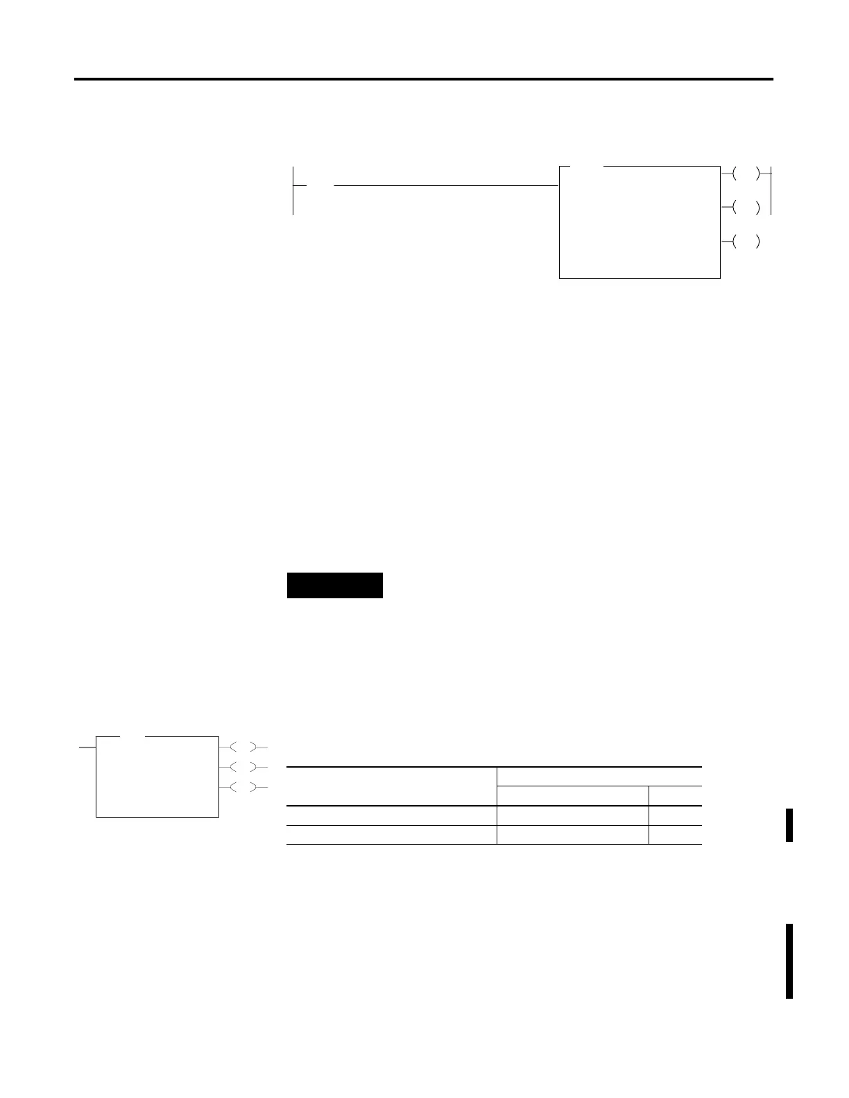
Example
In this example, when the rung goes from false-to-true, the control
element Enable (EN) bit is set. When the instruction is placed in the ASCII
queue, the Queue bit (EU) is set. The Running bit (RN) is set when the
instruction is executing. The DN bit is set on completion of the
instruction.
The controller sends 25 characters from the start of string ST37:42 to the
display device and then sends user-configured append characters. The
Done bit (DN) is set and a value of 27 is present in .POS word of the
ASCII control data file.
When an error is detected, the error code is written to the Error Code Byte
and the Error Bit (ER) is set. See ASCII Instruction Error Codes on
page 20-30 for a list of the error codes and recommended action to take.
AWT - ASCII Write
Instruction Type: output
Use the AWT instruction to write characters from a source string to an
external device.
Programming AWT Instructions
When programming ASCII output instructions, always precede the ASCII
instruction with conditional logic that either detects when new data needs
AWA
ASCII WRITE APPEND
Channel
Source
I:1
10
[
[
Control
0
ST37:42
R6:23
String Length
Characters Sent
25
0
EN
DN
ER
Error
00
If input slot 1, bit 10 is set, read 25 characters from
ST37:42 and write it to the display device. Then
write a carriage return and line feed (default).
NOTE
For information on the timing of this instruction, see the
timing diagram on page 20-28.
EN
DN
ER
AWT
ASCII Write
Channel 0
Source ST14:4
Control R6:1
String Length 40
Characters Sent 0
Error 0
AWT
Table 20.9 Execution Time for the AWT Instruction
Controller When Instruction Is:
True False
MicroLogix 1200 268
µ
s + 12
µ
s/character 14.1
µ
s
MicroLogix 1500 Series B, FRN 4 or later 237
µ
s + 10.6
µ
s/character 12.8
µ
s

 Loading...


