Publication 1762-RM001C-EN-P
Process Control Instruction 19-17
Analog I/O Scaling
To configure an analog input for use in a PID instruction, the analog data
must be scaled to match the PID instruction parameters. In the MicroLogix
1200 and 1500, the process variable (PV) in the PID instruction is
designed to work with a data range of 0 to 16,383. The 1769 Compact I/O
analog modules (1769-IF4 and 1769-OF2) are capable of on-board scaling.
Scaling data is required to match the range of the analog input to the
input range of the PID instruction. The ability to perform scaling in the
I/O modules reduces the amount of programming required in the system
and makes PID setup much easier.
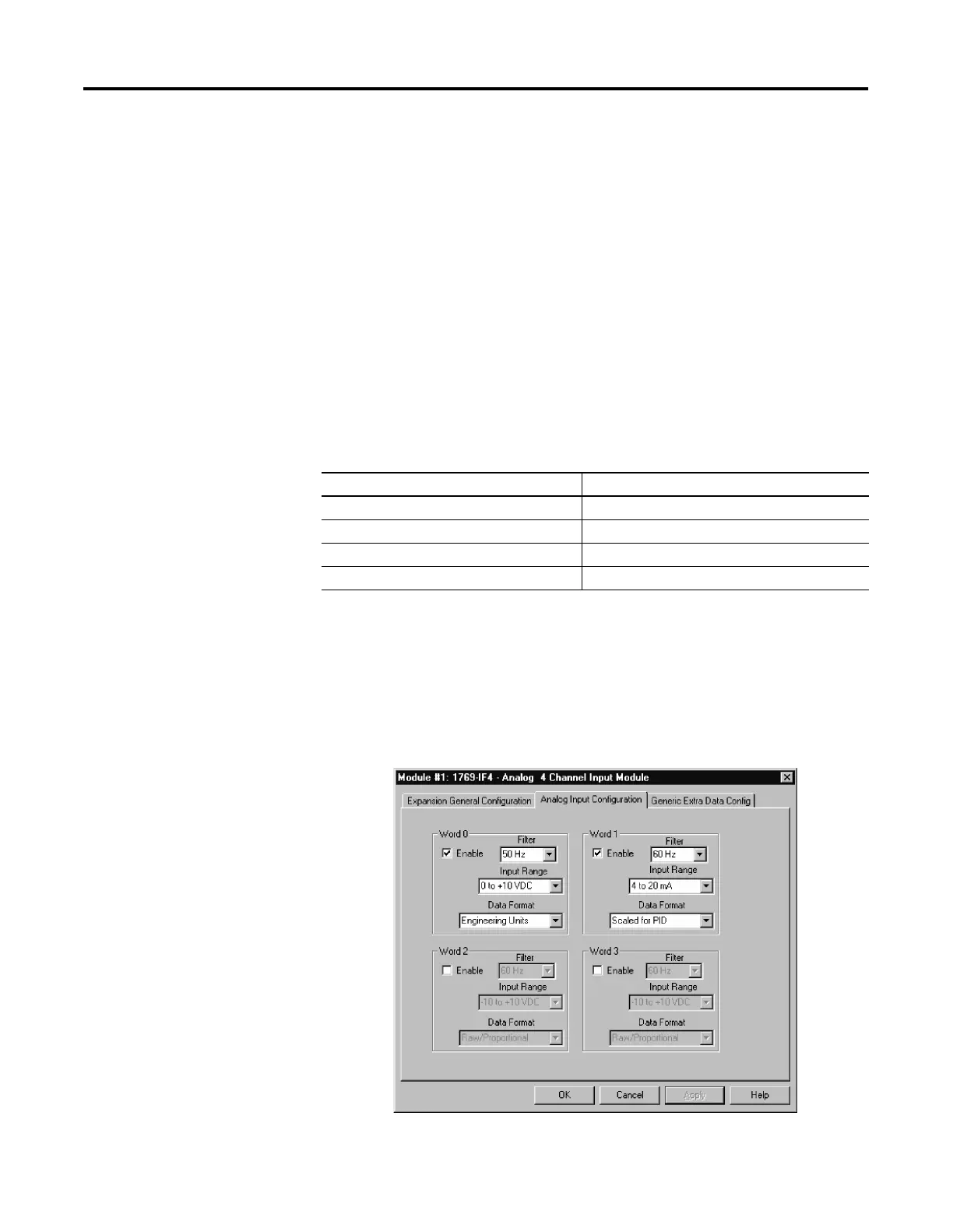
The example shows a 1769-IF4 module. The IF4 has 4 inputs, which are
individually configurable. In this example, analog input 0 is configured for
0 to 10V and is scaled in engineering units. Word 0 is not being used in a
PID instruction. Input 1 (word 1) is configured for 4 to 20 mA operation
with scaling configured for a PID instruction. This configures the analog
data for the PID instruction.
The analog configuration screen is accessed from within RSLogix 500.
Simply double click on the I/O configuration item in the “Controller”
folder, and then double click on the specific I/O module.
The configuration for the analog output is virtually identical. Simply
address the PID control variable (CV) to the analog output address and
configure the analog output to “Scaled for PID” behavior.
Field Device Input Signal Analog Register Scaled Data
> 20.0 mA 16,384 to 17,406
20.0 mA 16,383
4.0 mA 0
< 4.0 mA -819 to -1

 Loading...


