Publication 1762-RM001C-EN-P
10-8 Math Instructions
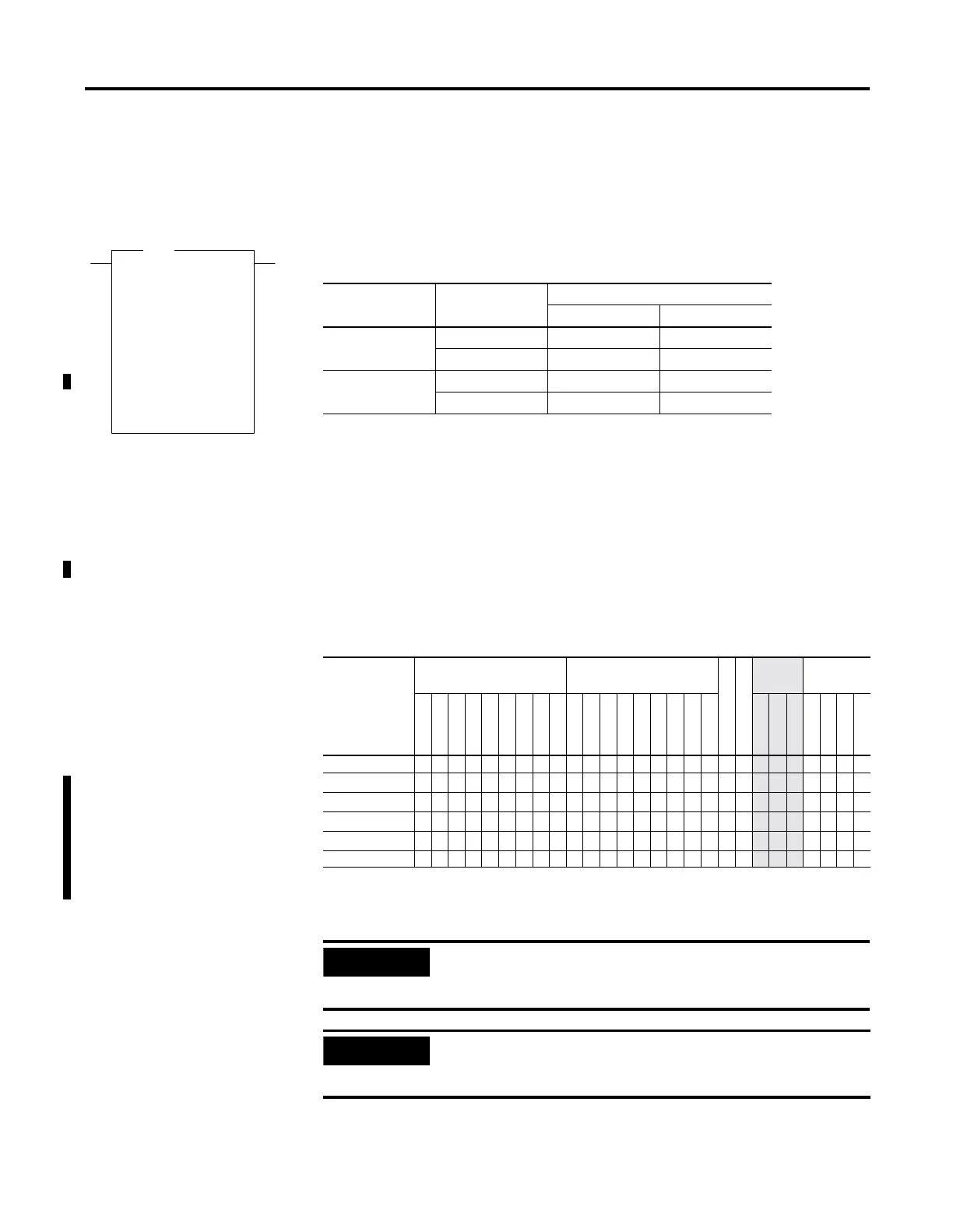
SCP - Scale with
Parameters
Instruction Type: output
The SCP instruction produces a scaled output value that has a linear
relationship between the input and scaled values. This instruction solves
the following equation listed below to determine scaled output:
y = [(y
1
- y
0
)/(x
1
- x
0
)](x - x
0
) + y
0
Addressing Modes and File Types can be used as shown in the following
table:
SCP
Scale w/Parameters
Input N7:0
0<
Input Min. N7:1
0<
Input Max. N7:2
0<
Scaled Min. N7:3
0<
Scaled Max. N7:4
0<
Output N7:5
0<
SCP
Table 10.9 Execution Time for the SCP Instruction
Controller Data Size When Rung Is:
True False
MicroLogix 1200 word 31.5
µ
s0.0
µ
s
long word 52.2
µ
s0.0
µ
s
MicroLogix 1500 word 27.0
µ
s0.0
µ
s
long word 44.7
µ
s0.0
µ
s
Table 10.10 SCP Instruction Valid Addressing Modes and File Types
For definitions of the terms used in this table see Using the Instruction Descriptions on page4-2.
Parameter
Data Files
Function Files
(1)
(1) DAT files are valid for the MicroLogix 1500 only. PTO and PWM files are only recommended for use with MicroLogix
1200 and 1500 BXB units.
CS - Comms
IOS - I/O
Address
Mode
(2)
(2) See Important note about indirect addressing.
Address
Level
O
I
S
B
T, C, R
N
ST
L
MG, PD
RTC
HSC
PTO, PWM
STI
EII
BHI
MMI
DAT
TPI
Immediate
Direct
Indirect
Bit
Word
Long Word
Element
Input (x) •••••• ••••••••••••• • •••
Input Min. (x
0
)
•• ••• •
• • •••
Input Max. (x
1
)
•• ••• •
• • •••
Scaled Min. (y
0
)
•• ••• •
• • •••
Scaled Max. (y
1
)
•• ••• •
• • •••
Output (y) •••••• ••• ••• •
• •••
IMPORTANT
You cannot use indirect addressing with: S, ST, MG, PD,
RTC, HSC, PTO, PWM, STI, EII, BHI, MMI, DAT, TPI, CS,
IOS, and DLS files.
IMPORTANT
Do not use the High Speed Counter Accumulator
(HSC.ACC) for the Scaled Output parameter in the SCP
instruction.

 Loading...


