1 Publication 1762-RM001C-EN-P
Chapter
8
Timer and Counter Instructions
Timers and counters are output instructions that let you control operations
based on time or a number of events. The following Timer and Counter
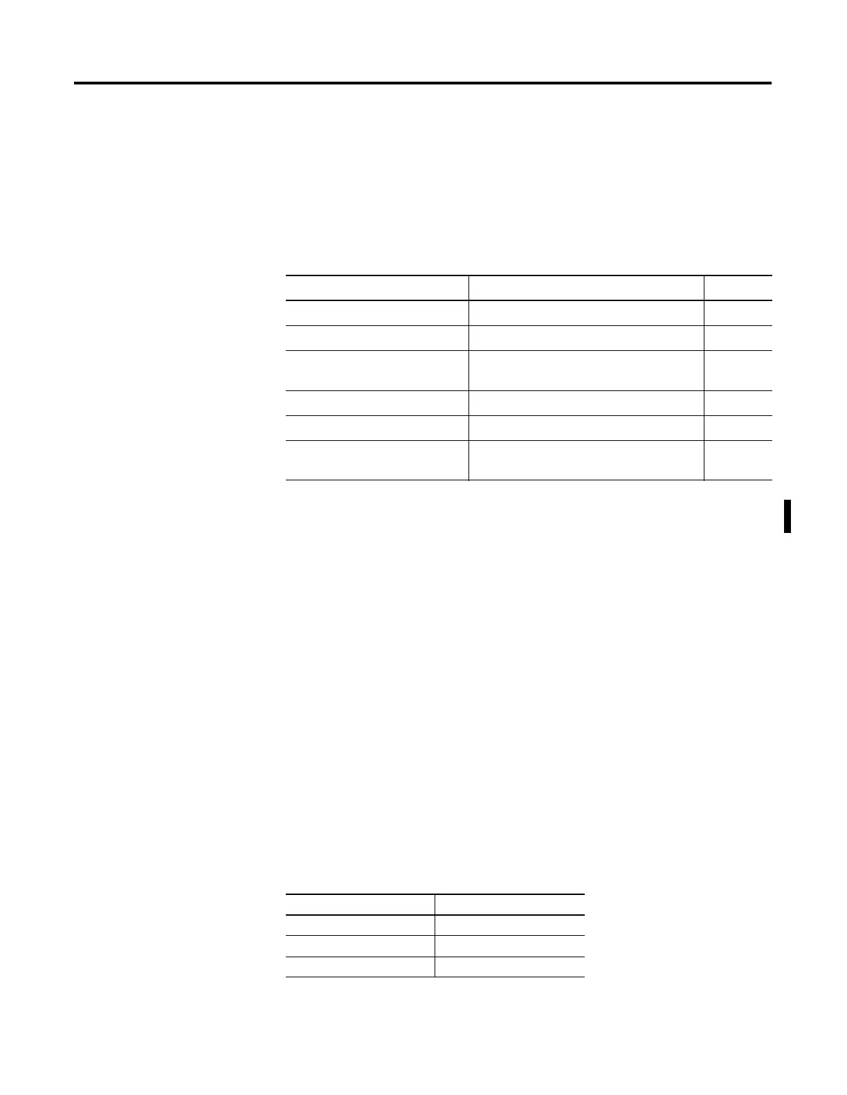
Instructions are described in this chapter:
For information on using the High-Speed Counter output(s), see Using the
High-Speed Counter on page 5-1.
Timer Instructions
Overview
Timers in a controller reside in a timer file. A timer file can be assigned as
any unused data file. When a data file is used as a timer file, each timer
element within the file has three sub-elements. These sub-elements are:
•
Timer Control and Status
•
Preset - This is the value that the timer must reach before the timer
times out. When the accumulator reaches this value, the DN status bit
is set (TON and RTO only). The preset data range is from 0 to 32767.
The minimum required update interval is 2.55 seconds regardless of
the time base.
•
Accumulator - The accumulator counts the time base intervals. It
represents elapsed time. The accumulator data range is from 0 to
32767.
Timers can be set to any one of three time bases:
Instruction Used To: Page
TON - Timer, On-Delay Delay turning on an output on a true rung 8-4
TOF - Timer, Off-Delay Delay turning off an output on a false rung 8-5
RTO - Retentive Timer On Delay turning on an output from a true rung.
The accumulator is retentive.
8-6
CTU - Count Up Count up 8-9
CTD - Count Down Count down 8-9
RES - Reset Reset the RTO and counter’s ACC and status
bits (not used with TOF timers).
8-10
Table 8.1 Timer Base Settings
Time Base Timing Range
0.001 seconds 0 to 32.767 seconds
0.01 seconds 0 to 327.67 seconds
1.00 seconds 0 to 32,767 seconds

 Loading...


