Publication 1766-RM001A-EN-P - October 2008
116 Using the High-Speed Counter and Programmable Limit Switch
Count Up (CU)
The CU (Count Up) bit is used with all of the HSCs (modes 0…9). If the
CE bit is set, the CU bit is set (1). If the CE bit is clear, the CU bit is cleared
(0).
HSC Mode (MOD)
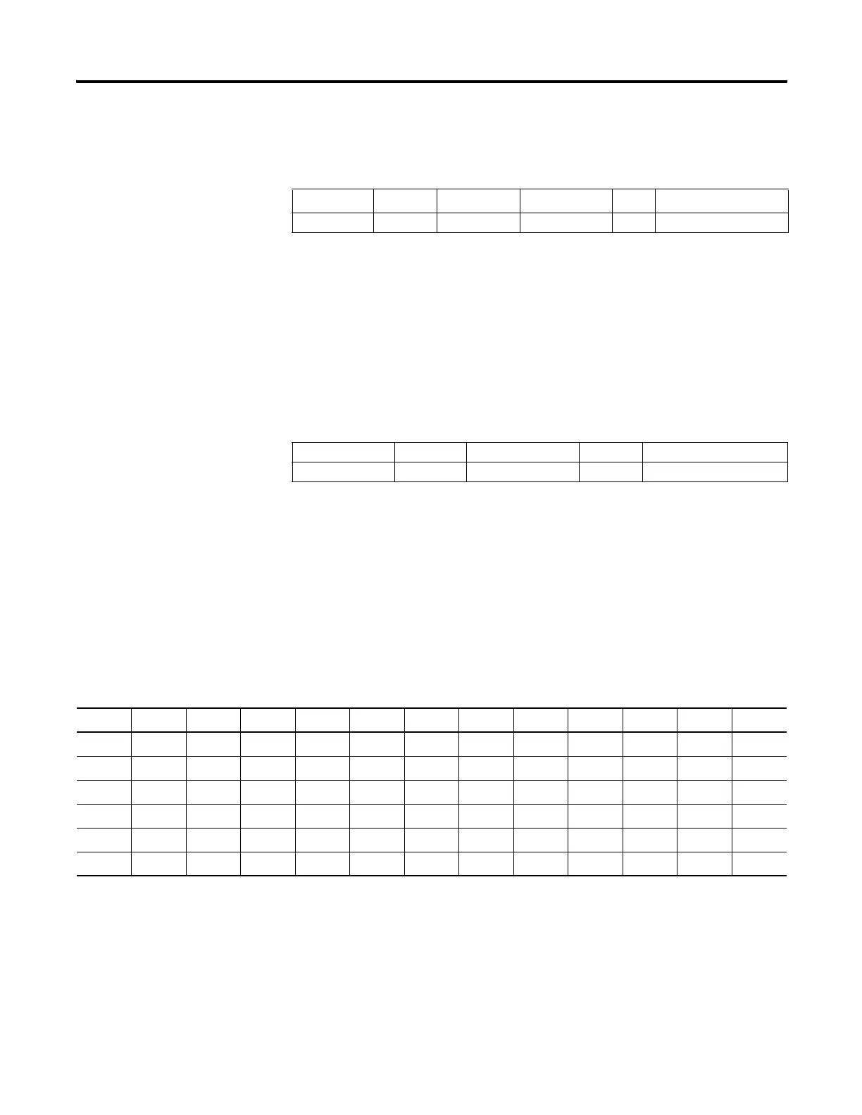
The MOD (Mode) variable sets the High-Speed Counter to one of 10 types
of operation. This integer value is configured through the programming
device and is accessible in the control program as a read-only variable.
HSC0's sub counter is HSC3, HSC1's sub counter is HSC4 and HSC2's sub
counter is HSC5. Each set of counters share the input. The following table
shows the dedicated inputs for the HSCs depending on the mode.
Description Address Data Format
HSC Modes
(1)
(1) For Mode descriptions, see HSC Mode (MOD) on page 116.
Type User Program Access
CU - Count Up HSC:0/CU bit 0…9 status read only
Description Address Data Format Type User Program Access
MOD - HSC Mode HSC:0.MOD word (INT) control read only
HSC Input Assignments
I:0.0/0 I:0.0/1 I:0.0/2 I:0.0/3 I:0.0/4 I:0.0/5 I:0.0/6 I:0.0/7 I:0.0/8 I:0.0/9 I:0.0/10 I:0.0/11
HSC:0 A/C B/D Reset Hold
HSC:1 A/C B/D Reset Hold
HSC:2 A/C B/D Reset Hold
HSC:3 A/C B/D
HSC:4 A/C B/D
HSC:5 A/C B/D
efesotomasyon.com - Allen Bradley,Rockwell,plc,servo,drive

 Loading...


