Rockwell Automation Publication 520-UM001A-EN-E - February 2013 11
Chapter 1
Installation/Wiring
This chapter provides information on mounting and wiring the PowerFlex 525
drive.
Most start-up difficulties are the result of incorrect wiring. Every precaution must
be taken to assure that the wiring is done as instructed. All items must be read and
understood before the actual installation begins.
Mounting Considerations
• Mount the drive upright on a flat, vertical and level surface.
• Protect the cooling fan by avoiding dust or metallic particles.
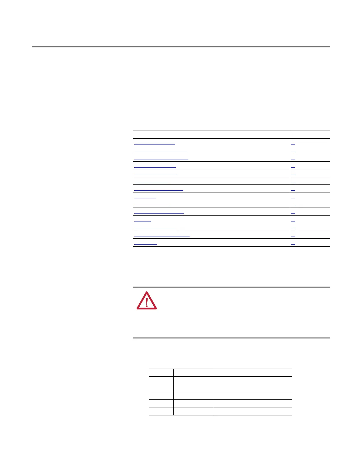
For information on... See page...
Mounting Considerations
11
AC Supply Source Considerations 15
General Grounding Requirements 16
Fuses and Circuit Breakers 18
Power and Control Module 22
Control Module Cover 25
Power Module Terminal Guard 25
Power Wiring 26
Power Terminal Block 29
Common Bus/Precharge Notes 30
I/O Wiring 30
Control I/O Terminal Block 32
Start and Speed Reference Control 39
CE Conformity 41
ATTENTION: The following information is merely a guide for proper
installation. Rockwell Automation cannot assume responsibility for the
compliance or the noncompliance to any code, national, local or otherwise for
the proper installation of this drive or associated equipment. A hazard of
personal injury and/or equipment damage exists if codes are ignored during
installation.
Frame Screw Size Screw Torque
A M5 (#10...24) 1.56...1.96 Nm (14...17 lb-in.)
B M5 (#10...24) 1.56...1.96 Nm (14...17 lb-in.)
C M5 (#10...24) 1.56...1.96 Nm (14...17 lb-in.)
D M5 (#10...24) 2.45...2.94 Nm (22...26 lb-in.)
E M8 (5/16 in.) 6.0...7.4 Nm (53...65 lb-in.)

 Loading...


