EasyManuals Logo
Home>Allen-Bradley>Controller>PowerFlex 700H

Allen-Bradley PowerFlex 700H Service Manual

Allen-Bradley PowerFlex 700H
115 pages
To Next Page IconTo Next Page
To Previous Page IconTo Previous Page
Page #104 background imageLoading...
Page #104 background image
C-8 Connector Descriptions
Hardware Connections
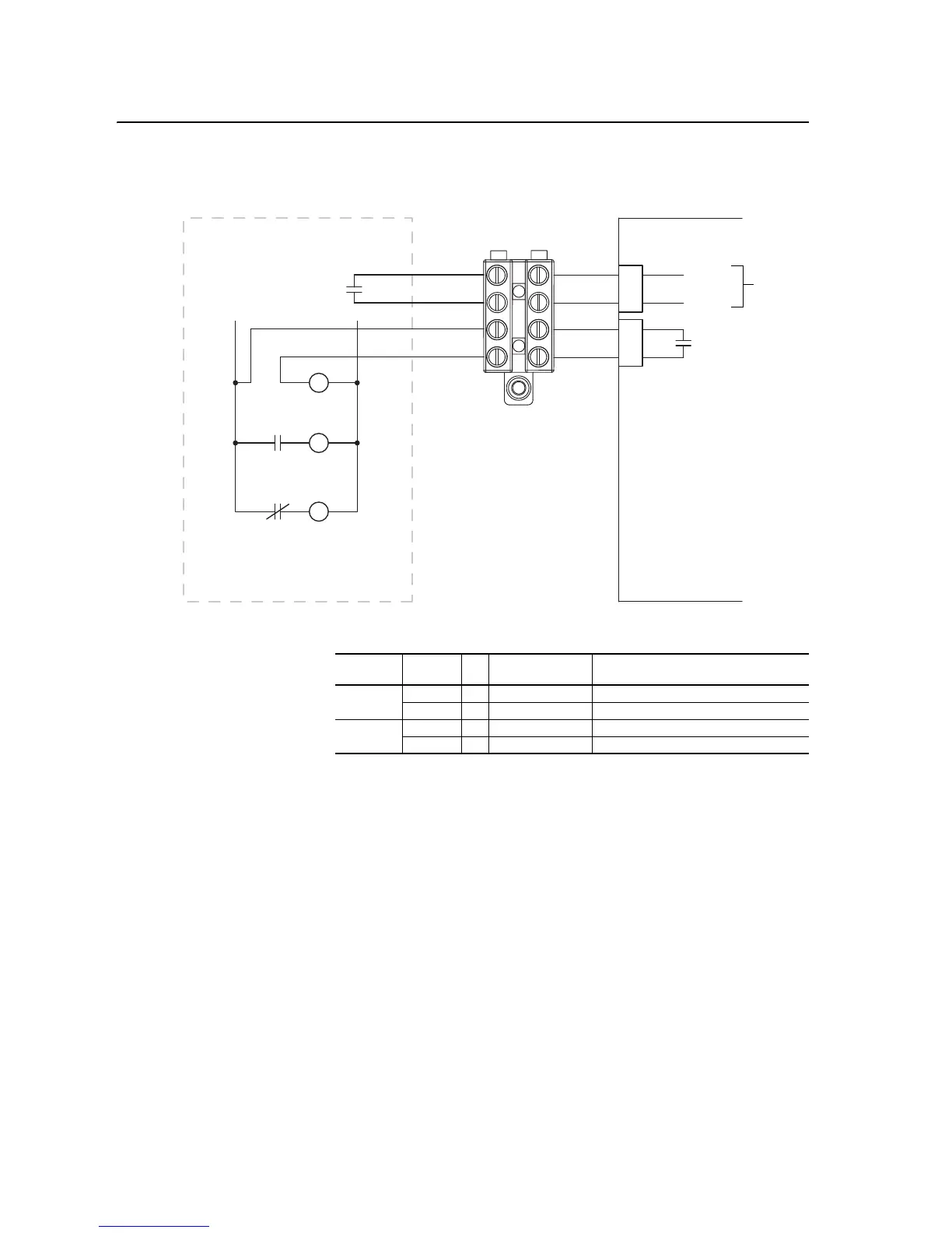
Figure C.7 X50 Terminal Block Connectors
Table C.M X50 Terminal Block Precharge Circuit Connections
Customer Connections Drive Connections
CR1
Pilot Relay
CR1
M
Main DC Contactor
M
CR2
Precharge
M
Example External Precharge Circuitry
For DC Input Only
(Do Not Install on AC Input Drives)
+24V DC
0V DC
1
2
3
4
25
26
21
23
X15
X9
ASIC BoardX50
Charge
Relay
Terminal Block on Control Pan
Isolated
ASIC Board
Connector Terminal to X50 Terminal Block Description
X9 25 . . . 1 Precharge Complete Signal
26 . . . 2 Precharge Complete Signal
X15 21 . . . 3 Charge Relay Contact
23 . . . 4 Charge Relay Contact

Table of Contents

Other manuals for Allen-Bradley PowerFlex 700H

Questions and Answers:

Question and Answer IconNeed help?

Do you have a question about the Allen-Bradley PowerFlex 700H and is the answer not in the manual?

Allen-Bradley PowerFlex 700H Specifications

General IconGeneral
BrandAllen-Bradley
ModelPowerFlex 700H
CategoryController
LanguageEnglish

Related product manuals