Access Procedures 3-17
Installation
Install the Protective Covers in reverse order of removal, while referring to
Torque Specifications on page 3-1
.
Removing the 700S Voltage
Feedback Circuit Board
Removal
1. Remove power from the drive. Refer to Removing Power from the
Drive on page 3-3.
2. Remove the covers from the power structures. Refer to Removing the
Covers from the Power Structure on page 3-13.
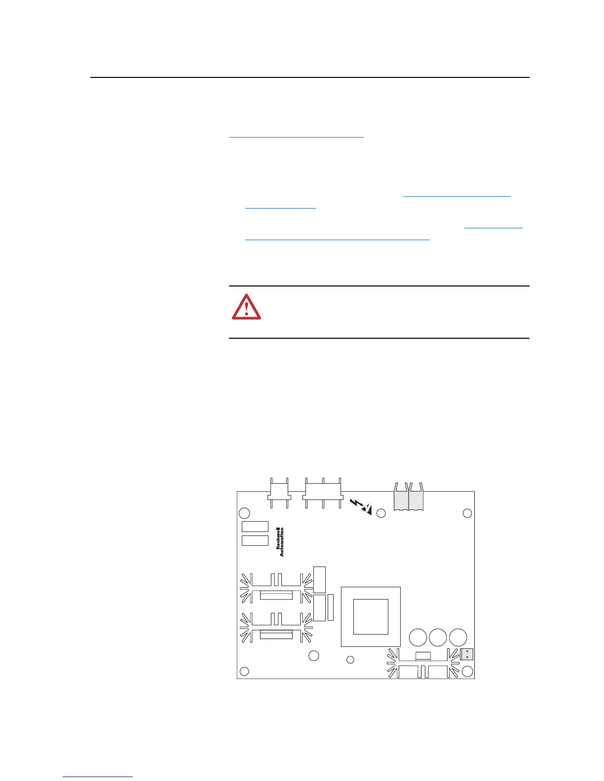
3. Carefully disconnect the fiber-optic cables from J4 and J5 sockets at the
top of the Voltage Feedback Circuit Board, and carefully set them aside.
Important: Minimum inside bend radius for fiber-optic cable is 25.4 mm (1
in.). Any bends with a shorter inside radius can permanently
damage the fiber-optic cable. Signal attenuation increases with
decreased inside bend radii.
4. Disconnect the DC bus connection cable from the J2 socket and the
motor feedback connection cable from the J3 socket at the top of the
Voltage Feedback Circuit Board.
5. Disconnect the cable from J8 socket of the Voltage Feedback Circuit
Board, and set it aside.
!
ATTENTION: Hazard of permanent eye damage exists when
using optical transmission equipment. This product emits intense
light and invisible radiation. Do not look into fiber-optic ports or
fiber-optic cable connectors.
J4 J5
J8
J2 J3

 Loading...


