3-4 Access Procedures
3. Measure the DC bus voltage at the DC+ & DC- terminals on the Power
Terminal Block. The voltage must be zero.
Removing the DPI / HIM
Assembly
Removal
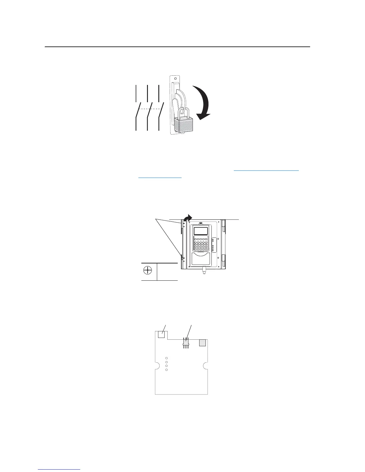
1. Remove power from the drive. Refer to Removing Power from the
Drive on page 3-3.
Important: Before removing connections and wires, mark the connections
and wires to avoid incorrect wiring during assembly.
2. Remove the two screws from the front of the DPI / HIM assembly.
3. Open the door, which holds the DPI interface and HIM.
4. Unplug the DPI cable from the X2 connector on the DPI Interface
Circuit Board.
5. On 700S drives only, unplug the cable from the X4 connector on the
circuit board.
L1 L2 L3
O
I
Screws
P1
0.9 N-m
(8 lb.-in.)
Back view of DPI
X4
X2
Circuit Board which
should remain mounted
on the back of
the assembly

 Loading...


