EasyManuals Logo
Home>Allen-Bradley>Controller>PowerFlex 700H

Allen-Bradley PowerFlex 700H Service Manual

Allen-Bradley PowerFlex 700H
115 pages
To Next Page IconTo Next Page
To Previous Page IconTo Previous Page
Page #94 background imageLoading...
Page #94 background image
B-10 Schematics
Circuit Board Connections for 700S Drives - Phase II Control with AC Input
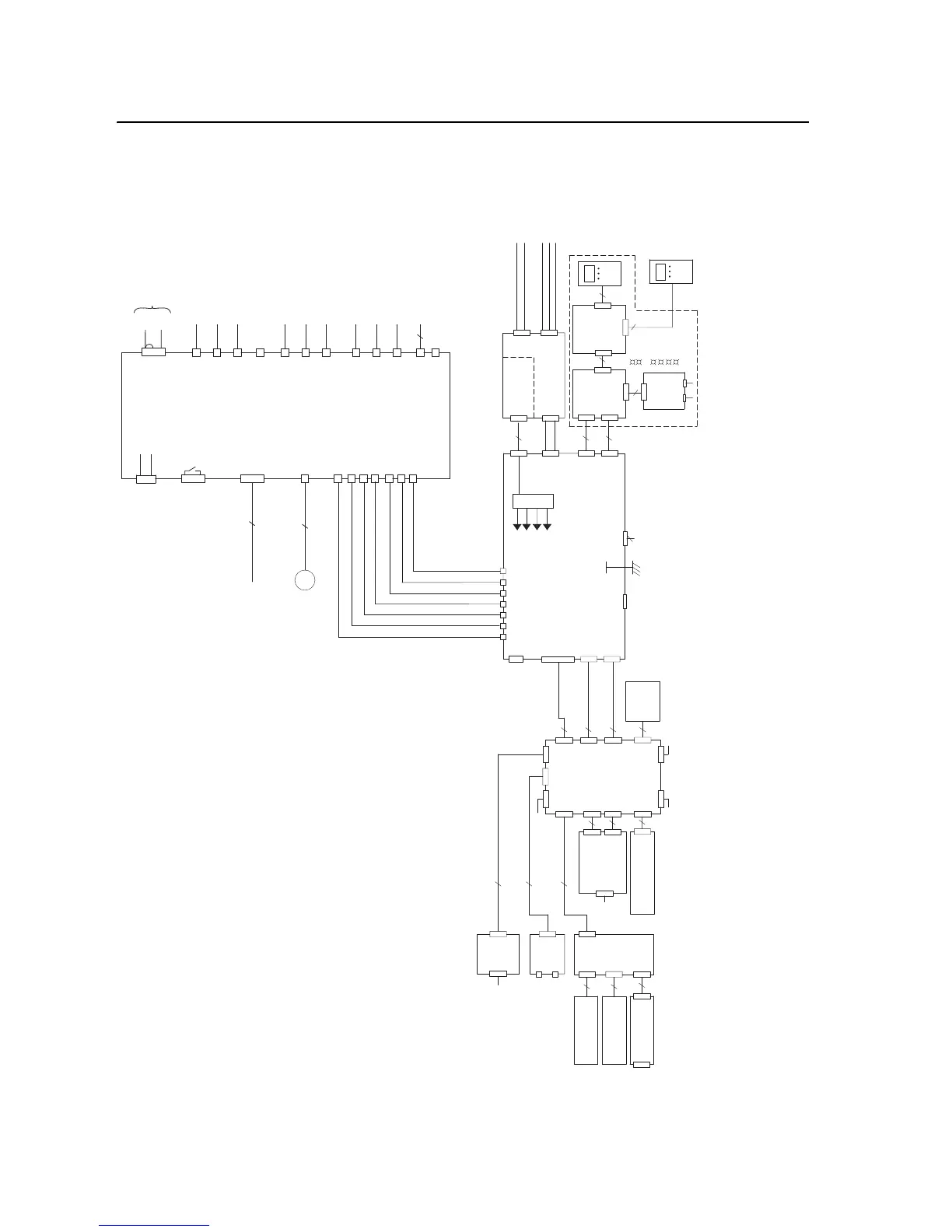
Figure B.9 Circuit Board Connections for 700S
Drives - Phase II Control with AC Input
W/T3 PHASE FROM SHEET
4
V/T2 PHASE FROM SHEET
3
U/T1 PHASE FROM SHEET
2
DC+ FROM SHEET 2
HiHP Fiber Optic
Interface Board
J17
J18
J15
J14
(Vbus Tx)
(Gate Enable)
J3
J8
J11
(V Gate)
(U Gate)
J10
J9
(ADconv)
(W Gate)
J12
-12 V
+12 V
+24 V Iso
(Vbus Rx)
+5V
J13
Fiber Optic Cables
NET B
DPI ASSEMBLY
20-VB00601
DPI
Comm
Option
DPI
Interface
Board
2
9
J16
J4
X4
X3
X2
NET A
PORT
MOD
20
PWR
STS
9
X1
J2
J3
J1
9
DPI
Bezel
External DPI
HIM
20-HIM-A3
Example:
DOOR
HIM
Voltage
Feedback
Board
2
Rx
J7
J6 Tx
J5
Rx J5
Tx J4
+24V
J8
J2
80 W
Power
Supply
-W
-V
-U
-DC+
-DC-
J1
DC- FROM SHEET 2
2
LED
Status
DPI
External
24 V DC
1=24V
3=Common
(75W min)
Fiber
9
8
8
9
M
ASIC Board Fan
X2
H13
H12
H11
H10
X4
H9
H8
X3
X6
ASIC
Board
X9
X15 Charge Relay
X11 (Fan Control)
X1
25
26
21
22
23
1
2
3
H1
H2
H3
H4
H5
H6
H7
To Fan Inverter X8
X5
To Phase U Gate Driver Board
X6 in Power Circuitry
To Phase U Gate Driver Board
H15 in Power Circuitry
To Phase U Gate Driver Board
H16 in Power Circuitry
To Phase V Gate Driver Board
X6 in Power Cirucitry
To Phase V Gate Driver Board
H15 in Power Circuitry
To Phase V Gate Driver Board
H16 in Power Circuitry
To Phase W Gate Driver Board
X6 in Power Circuitry
To Phase W Gate Driver Board
H15 in Power Circuitry
To Phase W Gate Driver Board
H16 in Power Circuitry
To Phase V Rectifier Board
X13 in Power Circuitry
Fiber Optic Cables
+24V
0EVA
3
5
2
DC-
DC+
From DC Bus in Power Circuitry
SECOND ENCODER
SAFE OFF OPTION
FDBK
OPTION
BOARD
COMPACT
FLASH OPTION
COM
I
NPUT
P2
P4
P3
OPTIONAL
P1
OPTION
I/O OPTION
COMPACT
COMM
80
50
INPUTS
FDBK
P1
LEOB
P1
OPTION
OPTION
TX
16
RX
CONNECTOR
P1
RJ45
P1
LINK
SYNC
120
P2
ENET
7
80
34
PHASE II
CONTROL
BOARD
WITH ALL
OPTIONS
SHOWN
BATTERY
P13
P2
TB1
P4
P3
P2
P12
16
P11
34
ELC
TB2
P5
P21
P1
P2
2
40
PORT
RS-232
P10
P3
P6
P7 P9
10
30
J1
J2
X29
X600

Table of Contents

Other manuals for Allen-Bradley PowerFlex 700H

Questions and Answers:

Question and Answer IconNeed help?

Do you have a question about the Allen-Bradley PowerFlex 700H and is the answer not in the manual?

Allen-Bradley PowerFlex 700H Specifications

General IconGeneral
BrandAllen-Bradley
ModelPowerFlex 700H
CategoryController
LanguageEnglish

Related product manuals