Access Procedures 3-3
Understanding Torque Figures in Assembly Diagrams
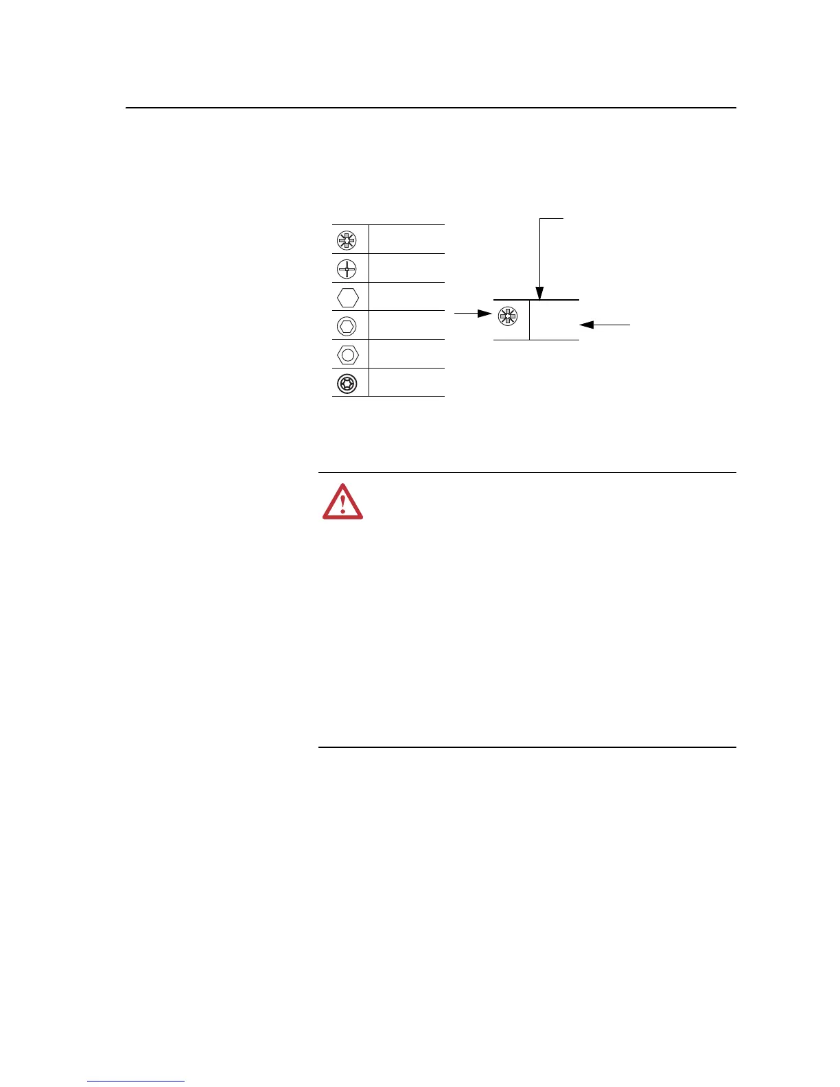
Icons and numbers in the assembly diagrams indicate how to tighten
hardware:
Removing Power from the
Drive
Removing Power
1. Turn off and lock out input power. Wait five minutes.
2. Verify that there is no voltage at the drive’s input power terminals.
PZ2
4 N-m
(35 lb.-in.)
Tool Type and Size
PZ indicates POZIDRIV screwdriver bit
P indicates Phillips screwdriver bit
Tightening Torque
Fastener Type
POZIDRIV Screw
Phillips Screw
Hexagonal Bolt
or Standoff
Hexagonal
Screw
Hexagonal Nut
Torx Head Screw
!
ATTENTION: To avoid an electric shock hazard, verify that the
voltage on the bus capacitors has discharged before performing
any work on the drive. Measure the DC bus voltage at the DC+ &
DC- terminals. The voltage must be zero.
Remove power before making or breaking cable connections.
When you remove or insert a cable connector with power
applied, an electrical arc may occur. An electrical arc can cause
personal injury or property damage by:
x sending an erroneous signal to your system’s field devices,
causing unintended machine motion
x causing an explosion in a hazardous environment
Electrical arcing causes excessive wear to contacts on both the
module and its mating connector. Worn contacts may create
electrical resistance.

 Loading...


