B-6 Schematics
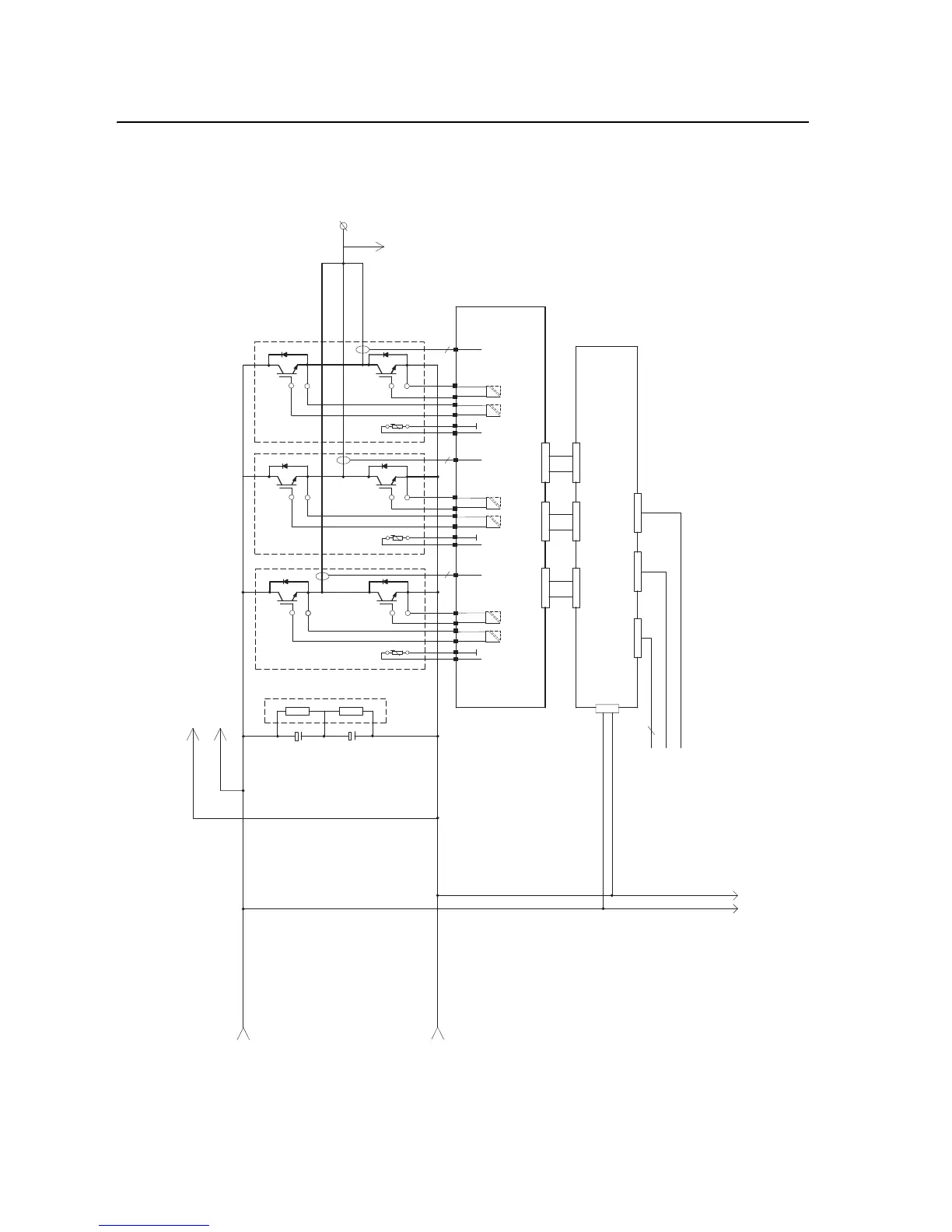
Phase V Power Circuitry for Drives with DC Input
Figure B.5 Phase V Power Circuitry for
Drives with DC Input
5
5
5
V/T2
I 3
TERM 3
I 2
I 1
TERM 2
TERM 1
Power Board
U_HI
U_LO
V_HI
V_LO
W_HI
W_LO
Driver Board
X1
To Voltage Feedback
Connaction J1
X6 X7 X8
X10 X11 X12
X6 H15 H16
Fiber Optic Cables
From ASIC X4
From ASIC X10
From ASIC H11
10
To U and
W Phase
DC-
DC+
See Note 1
Note 1 - 400V/600V Capacitor Configuration
400V - 3 Caps In Series, 2 Caps In Parallel
600V - 2 Caps In Series, 3 Caps In Parallel
DC-
DC+
To Fan

 Loading...


