2-18 Component Test Procedures
Checking the Main Fan
Inverters and Fans
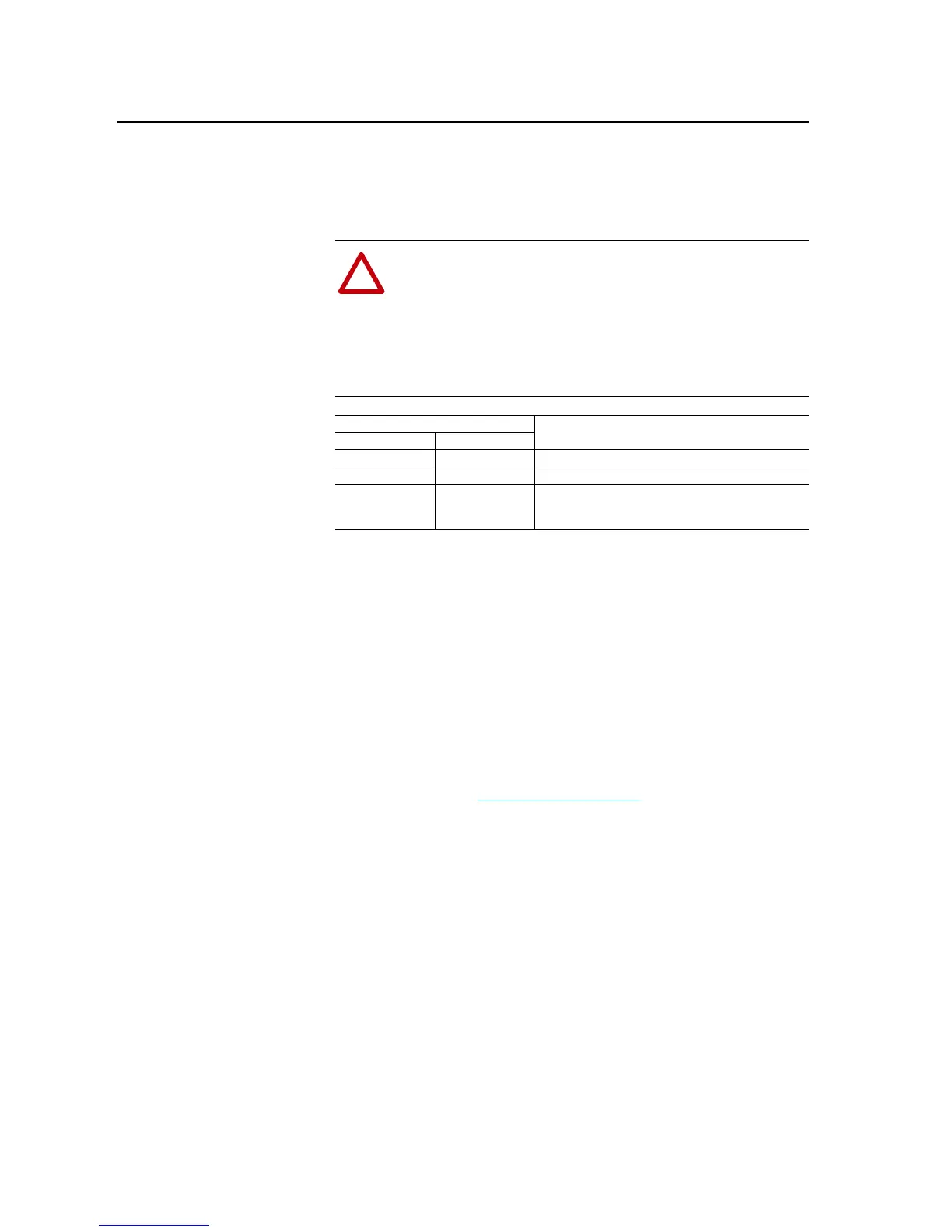
Checking Inverter LEDs
A frame 11 drive has three fans and three fan inverters. Each fan inverter has
a red and a green diagnostic LED.
Checking Fan Inverter Fuses
A pair of fuses (F1 and F2) feed DC Bus power to both inverters. Locate
these fuses and, using a multi-meter, verify that they are not open.
Isolating a Faulty Fan Inverter
The ASIC board controls all three fan inverters. A cable connects X11 on
the ASIC board to X8 on the first inverter. Another cable connects X3 of the
first inverter to X8 on the second inverter. Another cable connects X3 of the
second inverter to X8 on the third inverter. A jumper terminates X3 on the
third inverter. Refer to Figure B.11 on page B-12
. Use the following
procedure to isolate a faulty inverter if the main fans are not running:
1. Disconnect the cable from X3 of the second inverter.
2. Remove the jumper from X3 of the third inverter, and connect it to X3
of the second inverter.
3. Energize the drive. If only the fans on the first and second inverters run,
then the fan on the third inverter is faulty.
4. Disconnect the cable from X3 of the first inverter.
5. Remove the jumper from X3 of the third inverter, and connect it to X3
of the first inverter.
6. Energize the drive. If only the fans on the first and third inverters run,
then the fan on the second inverter is faulty. If none of the fans run, then
the first inverter is faulty.
!
ATTENTION: The inverter LEDs are only operational when
the drive is energized, and only visible with the covers removed
from the power structure. Servicing energized equipment can be
hazardous. Severe injury or death can result from electrical
shock, burn or unintended actuation of controlled equipment.
Follow Safety related practices of NFPA 70E, ELECTRICAL
SAFETY FOR EMPLOYEE WORKPLACES. DO NOT work
alone on energized equipment!
LED
IndicationRed Green
Steady Steady Inverter Idle
Off Flashing Inverter Running
Flashing Steady Inverter Faulted
or
No Control from ASIC board

 Loading...


