3-8 Access Procedures
Important: Minimum inside bend radius for fiber-optic cable is 25.4 mm (1
in.). Any bends with a shorter inside radius can permanently
damage the fiber-optic cable. Signal attenuation increases with
decreased inside bend radii.
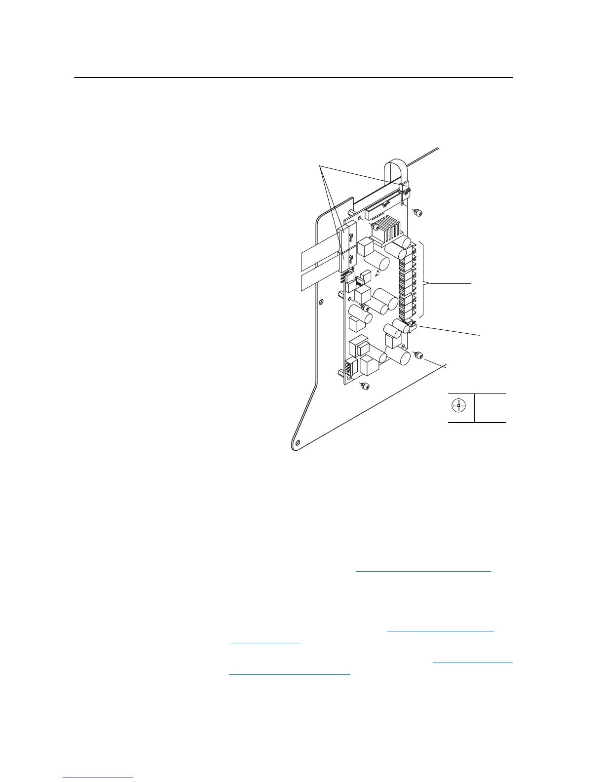
4. Remove the five screws which secure the High Power Fiber Optic
Interface Circuit Board to the Control Frame.
5. Remove the circuit board from the Control Frame.
Installation
Install the 700S High Power Fiber Optic Interface Circuit Board in reverse
order of removal, while referring to Torque Specifications on page 3-1
.
Removing the 700S Control
Assembly
Removal
1. Remove power from the drive. Refer to Removing Power from the
Drive on page 3-3.
2. Remove the 700S Main Control Assembly. Refer to Removing the 700S
Control Assembly on page 3-5.
Screws
Ribbon Cables
(5)
P1
0.9 N-m
(8 lb.-in.)
Fiber-Optic
Sockets
J5
Phase II Control Shown

 Loading...


