3-18 Access Procedures
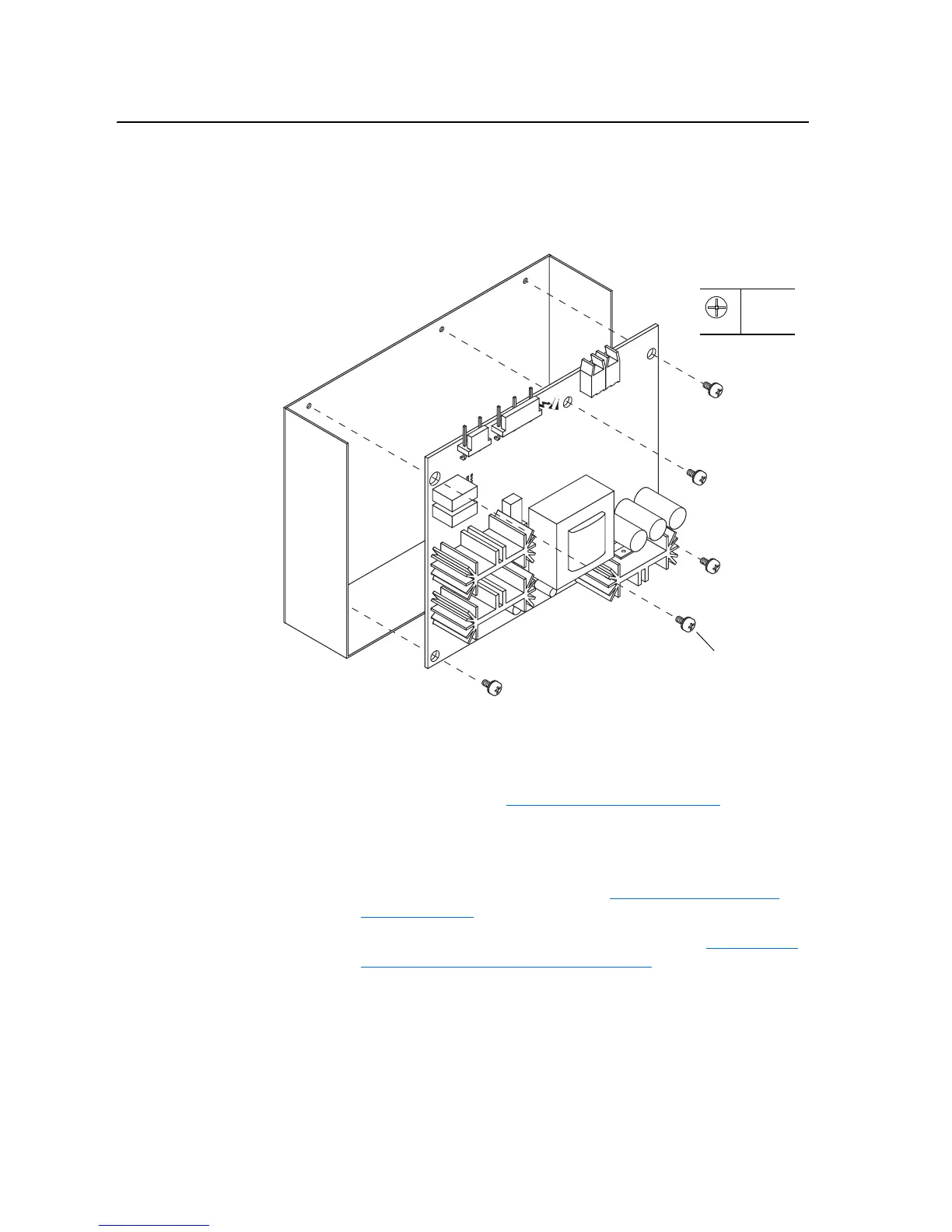
6. Remove the five screws which secure the Voltage Feedback Circuit
Board to the drive.
7. Remove the circuit board from the drive.
Installation
Install the 700S Voltage Feedback Circuit Board in reverse order of
removal, while referring to Torque Specifications on page 3-1
.
Removing the Gate Driver
Board
Removal
1. Remove power from the drive. Refer to Removing Power from the
Drive on page 3-3.
2. Remove the covers from the power structures. Refer to Removing the
Covers from the Power Structure on page 3-13.
3. Disconnect the DC +/- supply from X1 of the Gate Driver Board.
Screws
(5)
P1
0.9 N-m
(8 lb.-in.)

 Loading...


