Access Procedures 3-29
Removing the U Phase
(Left-Side) Output Power
Module
Removal
Important: Do not attempt to disassemble the Output Power Module.
Important: Always replace all three Output Power Modules (do not replace
just one module).
1. Remove power from the drive. Refer to Removing Power from the
Drive on page 3-3.
2. Remove the covers from the power structures. Refer to Removing the
Covers from the Power Structure on page 3-13.
3. Remove the power structure from the drive cabinet. Refer to Removing
the Power Structure from the Drive Cabinet on page 3-21.
4. Disconnect the output leads from the bottom of the Output Power
Module.
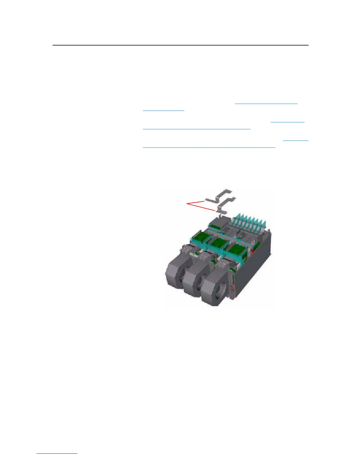
5. Remove the screws that secure the DC Bus Bars connecting the Input
Power Terminals to the Main DC Bus Bars and remove the Bus Bars.
6. Disconnect the rectifying circuit wiring from the Main DC Bus Bars.
DC Bus Bars

 Loading...


