3-36 Access Procedures
Removing the W Phase
(Right-Side) Rectifying
Board, Rectifying Module
and Output Power Module
Important: Do not attempt to disassemble the Output Power Module.
Important: Always replace all three Output Power Modules (do not replace
just one module).
1. Remove power from the drive (Removing Power from the Drive on
page 3-3).
2. Remove the covers from the power structures. Refer to Removing the
Covers from the Power Structure on page 3-13.
3. Remove the power structure from the drive cabinet (Removing the
Power Structure from the Drive Cabinet on page 3-21).
4. Disconnect the output leads from the bottom of the Output Power
Module.
5. Remove the screws that secure the W Phase (right-side) Power
assembly to the drive and remove the Power assembly.
Important: For 690V 460A and 502A units, the W Phase (right-side)
Power assembly does not have a Rectifying Module.
6. Disconnect all the wiring from the Rectifying Board and carefully set it
aside.
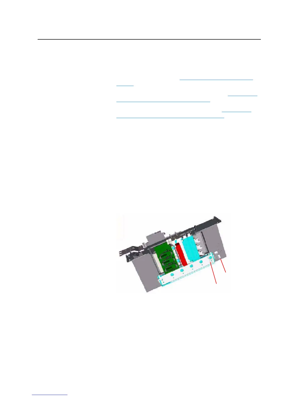
7. Remove the balancing resistor wires from bus bars.
8. Disconnect the cables from the AC input terminals on the Rectifying
Module.
Balancing Resistors
Balancing Resistor Wires

 Loading...


