Access Procedures 3-21
6. Disconnect the other cables from sockets on the front of the ASIC
Board, and set them aside.
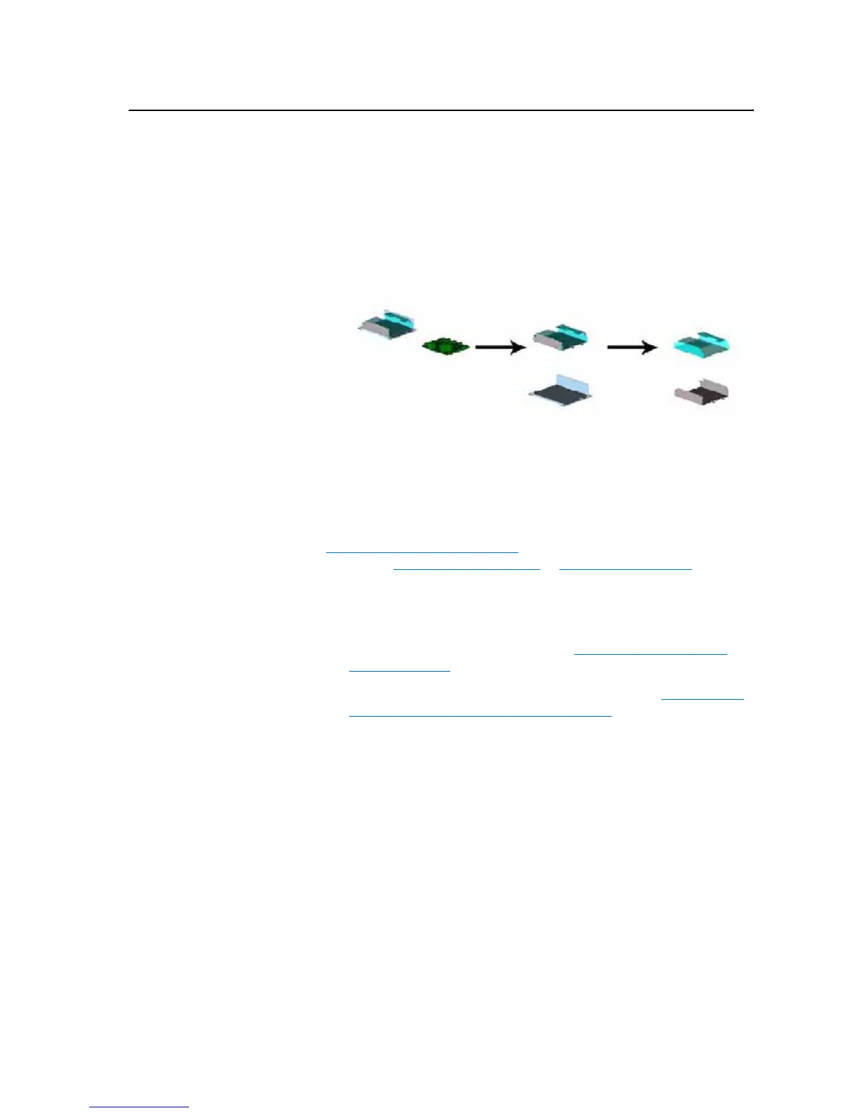
7. Remove the fan from the ASIC Board.
8. Slide the ASIC Board out of the assembly chassis.
9. Remove the ASIC assembly chassis from the mounting plate.
10. Remove the plastic board holder.
Installation
Install the ASIC Board in reverse order of removal, while referring to
Torque Specifications on page 3-1
. Reconnect cables to ASIC Board, while
referring to Figure B.10 on page B-11
or Figure B.7 on page B-8).
Removing the Power
Structure from the Drive
Cabinet
Removal
1. Remove power from the drive. Refer to Removing Power from the
Drive on page 3-3.
2. Remove the covers from the power structures. Refer to Removing the
Covers from the Power Structure on page 3-13.
3. Remove the motor wiring from the power structure at the front of the
power structure.
4. Remove the ground connection from the lower right corner of the power
structure.

 Loading...


