2-8 Component Test Procedures
Gate Interface Resistance
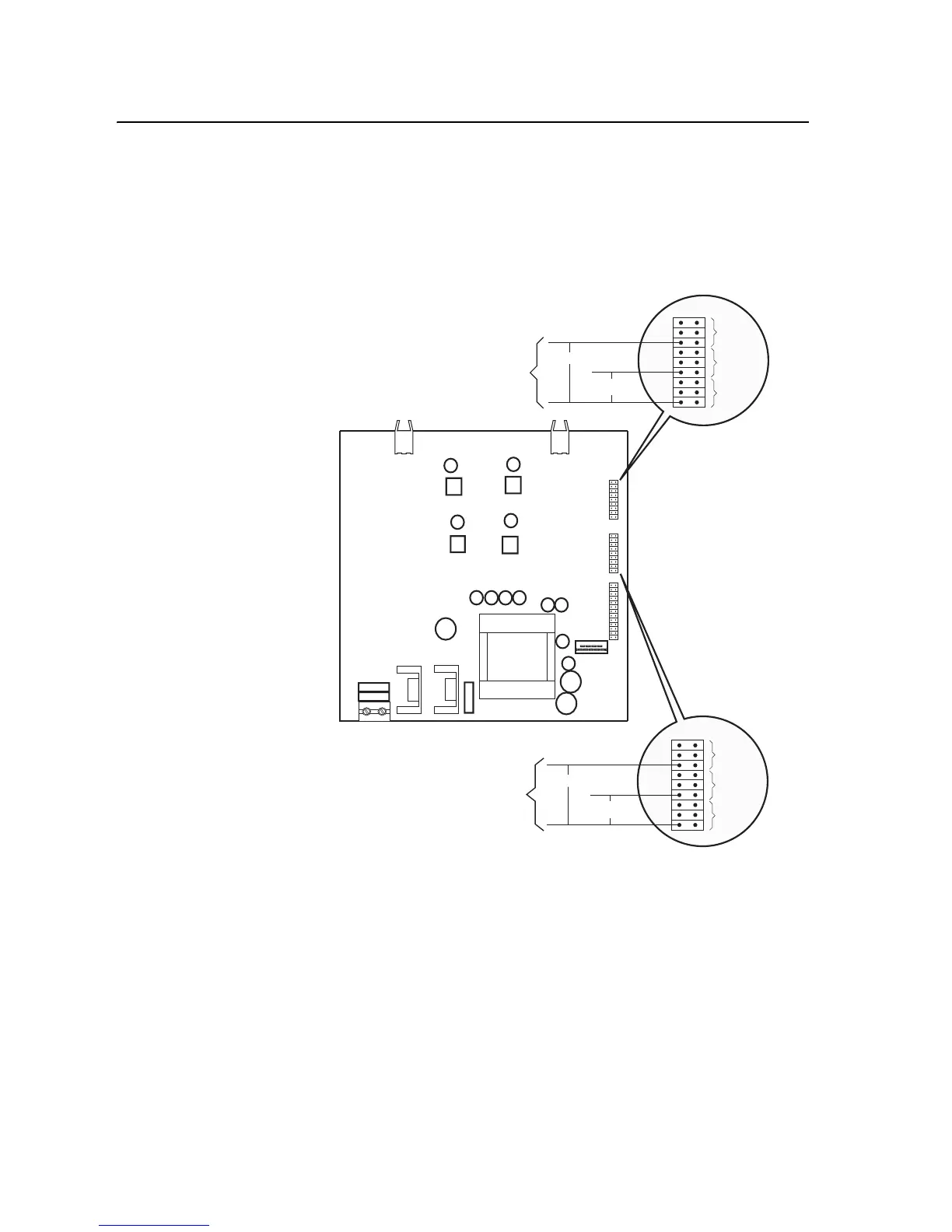
There are three Gate Driver boards, one per output power module. Measure
the gate interface resistance for each output power transistor. The resistance
from each gate and collector pin to the branch emitter pin should be about
333 ohms. If any of the gate interfaces fails this test, replace the appropriate
(left, middle, or right) output power module.
Preparing the Drive for Active Measurements on the Gate Driver Board
Important: This procedure requires special equipment and training. Only
qualified and trained personnel should perform these
procedures. If you do not have the special equipment, replace
the Gate Driver board to determine if the board is
malfunctioning.
Important: A High Voltage DC Test Power Supply is required to perform
these tests.
X1
HL
X10
~333 ohms
~333 ohms
Gate Interface for
U, V or W High (H)
Emitter
+/- 15 V
+/- 15 V
X11
~333 ohms
~333 ohms
Gate Interface for
U, V or W Low (L)
Emitter
+/- 15 V
+/- 15 V

 Loading...


