D-2 Disassembly / Assembly Diagrams
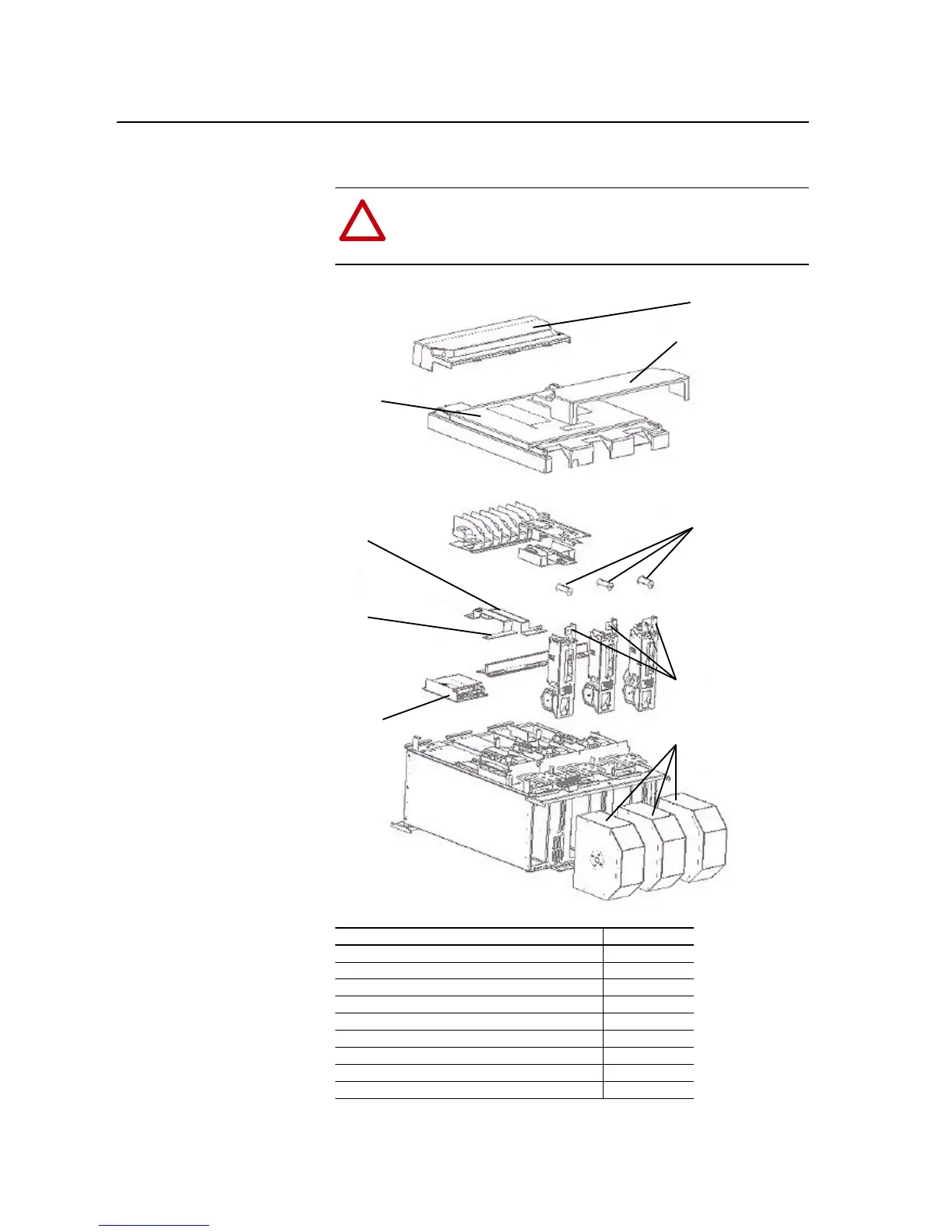
Figure D.1 Main Power Structure Assembly
Table D.A Main Power Structure Assembly Part Numbers
!
ATTENTION: The sheet metal cover and mounting screws on the
ASIC Board located on the power structure are energized at (-) DC bus
potential high voltage. Risk of electrical shock, injury, or death exists if
someone comes into contact with the assembly.
Part Name Spare Part No.
ASIC Assembly Upgrade Kit (without the ASIC Board) NA
Capacitor 7Pf 450V ac 20-PP00060
Connection Cover, Bottom NA
Connection Cover, Top NA
Intervening DC+ Bus Bar NA
Intervening DC- Bus Bar NA
Main Fan Assembly 230W 20-PP01080
Main Terminal Cover NA
Output Transformer Assembly for Fan Inverter 20-FR10845
Connection Cover, Top
Connection Cover, Bottom
Main Terminal
Cover
Intervening
DC+ Bus
Bar
Intervening
DC- Bus
Bar
Capacitor 7Pf 450V ac
ASIC
Assembly
Upgrade Kit
(without ASIC
Board)
Output Transformer
Assembly for Fan Inverter
Main Fan Assembly 230W

 Loading...


