3-38 Access Procedures
12. Remove the screws that secure the Rectifying Module to the power
structure and remove the Rectifying Module.
13. Remove the screws that secure the Output Power Module to the power
structure, and remove the Output Power Module.
Installation
Install the Output Power Module in reverse order of removal, while
referring to Torque Specifications on page 3-1
.
Removing the DC Bus
Capacitors
Removal
1. Remove power from the drive. Refer to Removing Power from the
Drive on page 3-3.
2. Remove the covers from the power structures. Refer to Removing the
Covers from the Power Structure on page 3-13.
3. Remove the power structure from the drive cabinet. Refer to Removing
the Power Structure from the Drive Cabinet on page 3-21.
4. Remove the Rectifying Module and Output Power Module. Refer to
Removing the U Phase (Left-Side) Output Power Module on page 3-29
,
Removing the V Phase (Middle) Rectifying Board, Rectifying Module
and Output Power Module on page 3-33, and Removing the W Phase
(Right-Side) Rectifying Board, Rectifying Module and Output Power
Module on page 3-36.
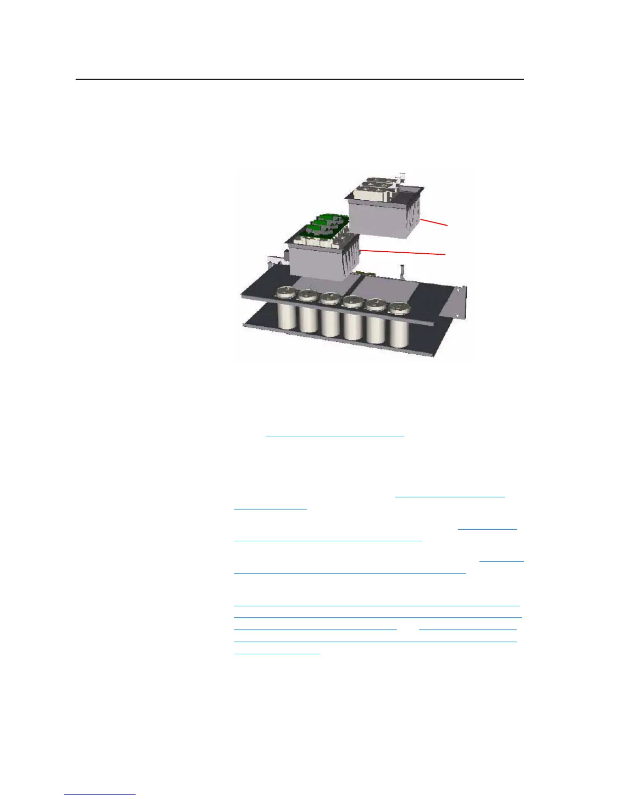
Important: It is not necessary to remove the Rectifying Board, Rectifying
Module, or Output Power Module in order to remove the DC
Bus Capacitors.
Rectifying Module
Output Power Module

 Loading...


