Design a sequential function chart
20 Rockwell Automation Publication 1756-PM006I-EN-P - February 2018
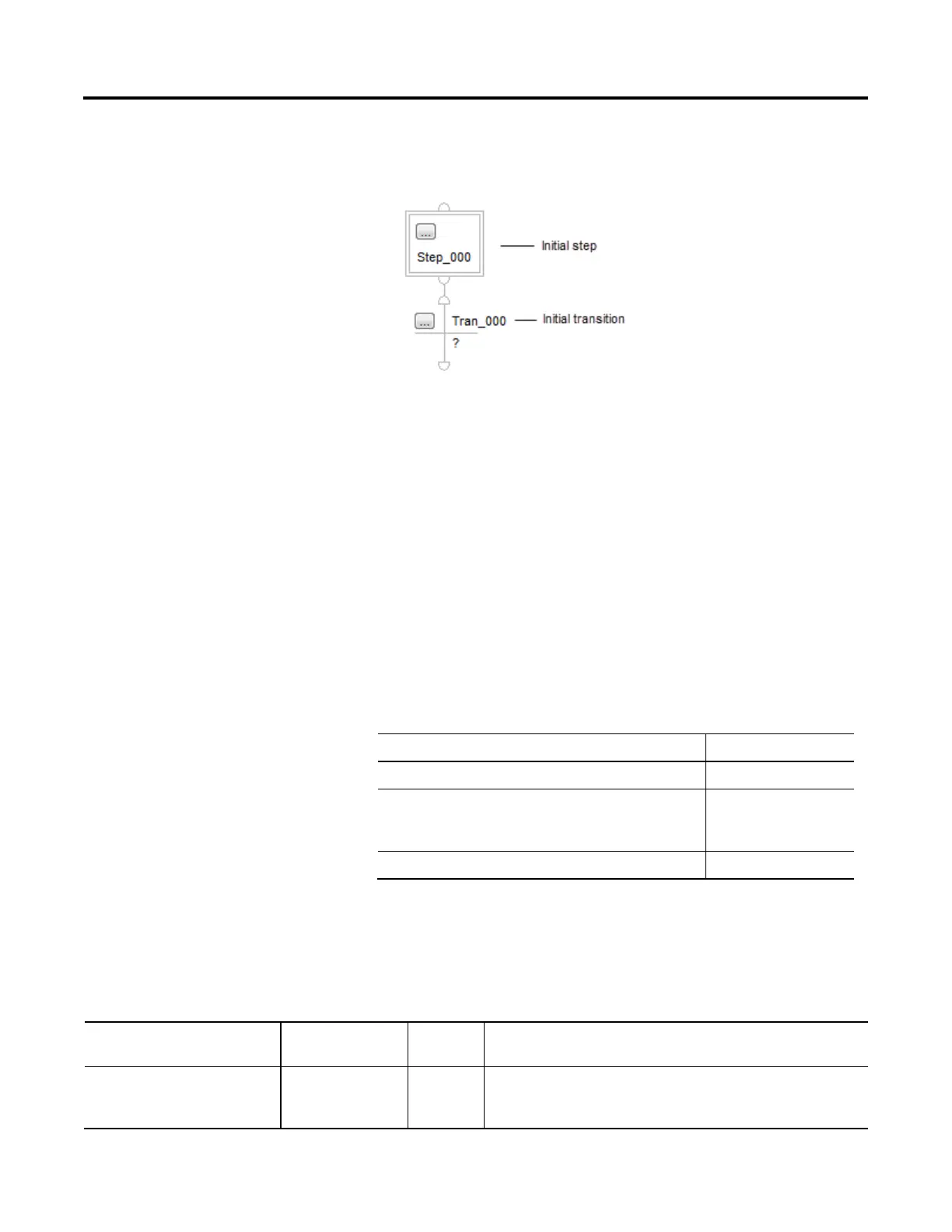
• When you first open an SFC routine, it contains an initial step and
transition. Use this step to initialize your process.
The controller executes the initial step in these situations.
• After a project download when the controller goes into Run mode.
• When the controller transitions to Run mode and on power-up (if the
SFC is configured for that).
• When the routine containing the chart is modified online and a reset is
required, and the controller transitions to or from Test mode.
• To identify a step, look for a physical change in your system, such as new
part that is in position, a temperature that is reached, a preset time that is
reached, or a recipe selection that occurs. The step is the actions that take
place before that change.
• Stop refining the steps when they are in meaningful increments. This is an
example.
This organization of steps Is
produce_solution Probably too large
set_mode, close_outlet, set_temperature, open_inlet_a, close_inlet_a,
set_timer, reset_temperature, open_outlet, reset_mode
Probably too small
preset_tank, add_ingredient_a, cook, drain Probably about right
Each step uses a tag to provide information about the step. Access this
information with either the Step Properties dialog box or the Monitor Tags tab
of the Tags window.
If you want to
Then select or set this
member
Data type Details
Determine how long a step has been active
(milliseconds)
T DINT
When a step becomes active, the Timer (T) value resets and then starts to count up in
milliseconds. The Timer continues to count up until the step goes inactive, regardless of
the Preset (PRE) value.
 Loading...


