MediaPack SIP User’s Manual 3. Installing the MediaPack
Version 4.6 35 June 2005
Table 3-2: Pin Allocation in the 50-pin Telco Connector
Phone Channel Connector Pins Phone Channel Connector Pins
1 1/26 13 13/38
2 2/27 14 14/39
3 3/28 15 15/40
4 4/29 16 16/41
5 5/30 17 17/42
6 6/31 18 18/43
7 7/32 19 19/44
8 8/33 20 20/45
9 9/34 21 21/46
10 10/35 22 22/47
11 11/36 23 23/48
12 12/37 24 24/49
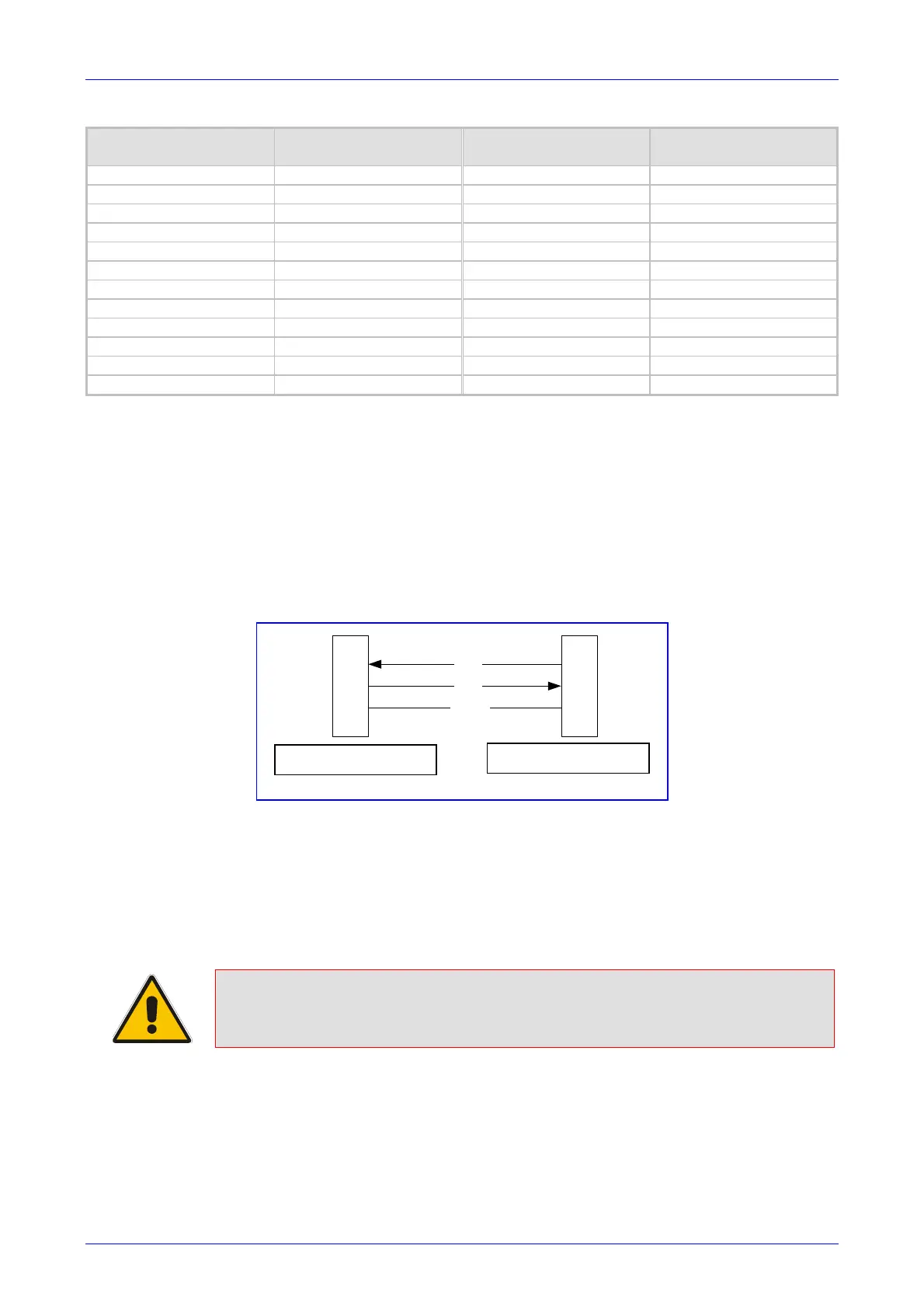
3.1.3.1 Connecting the MP-1xx RS-232 Port to Your PC
Using a standard RS-232 straight cable (not a cross-over cable) with DB-9 connectors, connect
the MP-1xx RS-232 port to either COM1 or COM2 RS-232 communication port on your PC. The
required connector pinout and gender are shown below in Figure
3-9.
For information on establishing a serial communications link with the MP-1xx, refer to Section
10.2 on page 201.
Figure
3-9: MP-1xx RS-232 Cable Wiring
2
3
5
2
3
5
RD
TD
GND
DB-9 female for PC DB-9 male for MP-100
3.1.3.2 Cabling the Lifeline Phone
The Lifeline provides a wired analog POTS phone connection to any PSTN or PBX FXS port
when there is no power, or when the network connection fails. Users can therefore use the
Lifeline phone even when the MP-1xx is not powered on or not connected to the network. With
the MP-108/FXS and MP-104/FXS the Lifeline connection is provided on port #4 (refer to Figure
3-11). With the MP-102/FXS the Lifeline connection is provided on port #2.
Note: The MP-124 and MP-10x/FXO do not support the Lifeline.
The Lifeline’s Splitter connects pins #1 and #4 to another source of an FXS port, and pins #2 and
#3 to the POTS phone. Refer to the Lifeline Splitter pinout in Figure
3-10.
DB-9 female for PC
DB-9 male for MP-1xx

 Loading...