ctrlX SAFETY "SafeMotion"
Specifying the digital/analog inputs/outputs
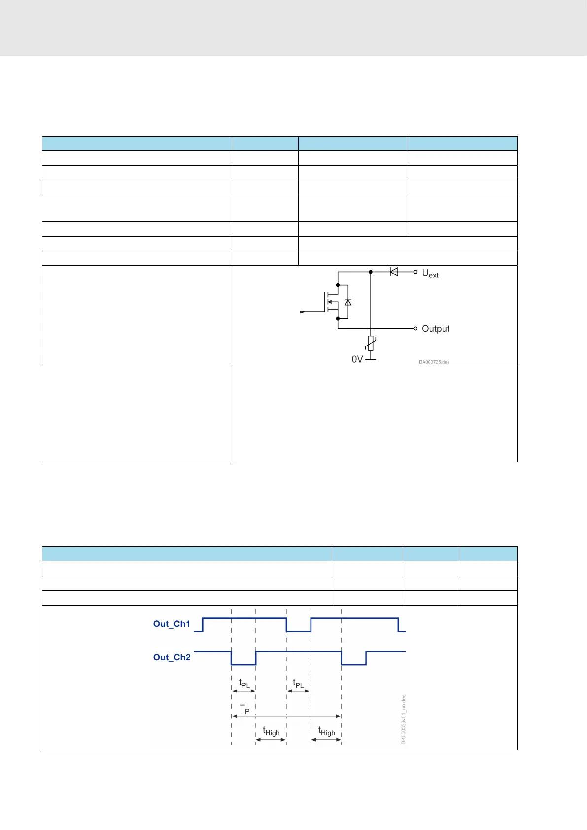
13.5.4 Digital outputs (safety technology SafeMotion)
The digital outputs are compatible with digital inputs of types 1, 2 and 3
(IEC 61131–2).
Table 54: Data
Data Unit min. max.
Output voltage ON V U
ext
- 1 U
ext
Output voltage OFF V 2
Allowed output current per output mA 350
Allowed energy content of connected
inductive loads, e.g. relay coils
mJ 400
1) 2)
capacitive load nF 200
Short circuit protection Available
Overload protection Available
Simplified diagram of output:
Error detection The following errors are detected:
● Wiring error with short circuit after High
●
Wiring error with short circuit after Low
●
Wiring error with short circuit between both channels
●
Internal error
In the case of an error, the control panel shows the corre-
sponding error message: F83xx
1) At a maximum switching frequency of 1 Hz
2) In the case of inductive loads with currents > 200 mA or in the case of
inductive loads with a greater energy content, an external free-wheeling arm
has to be installed. The active clamping voltage has to be < 25 V.
Table 55: Time response
Designation Unit min. max.
Test pulse width (t
PL
) μs 50 200
Cycle duration (T
P
) ms 500 1000
Time between two test pulses (t
High
) ms 50 -

 Loading...