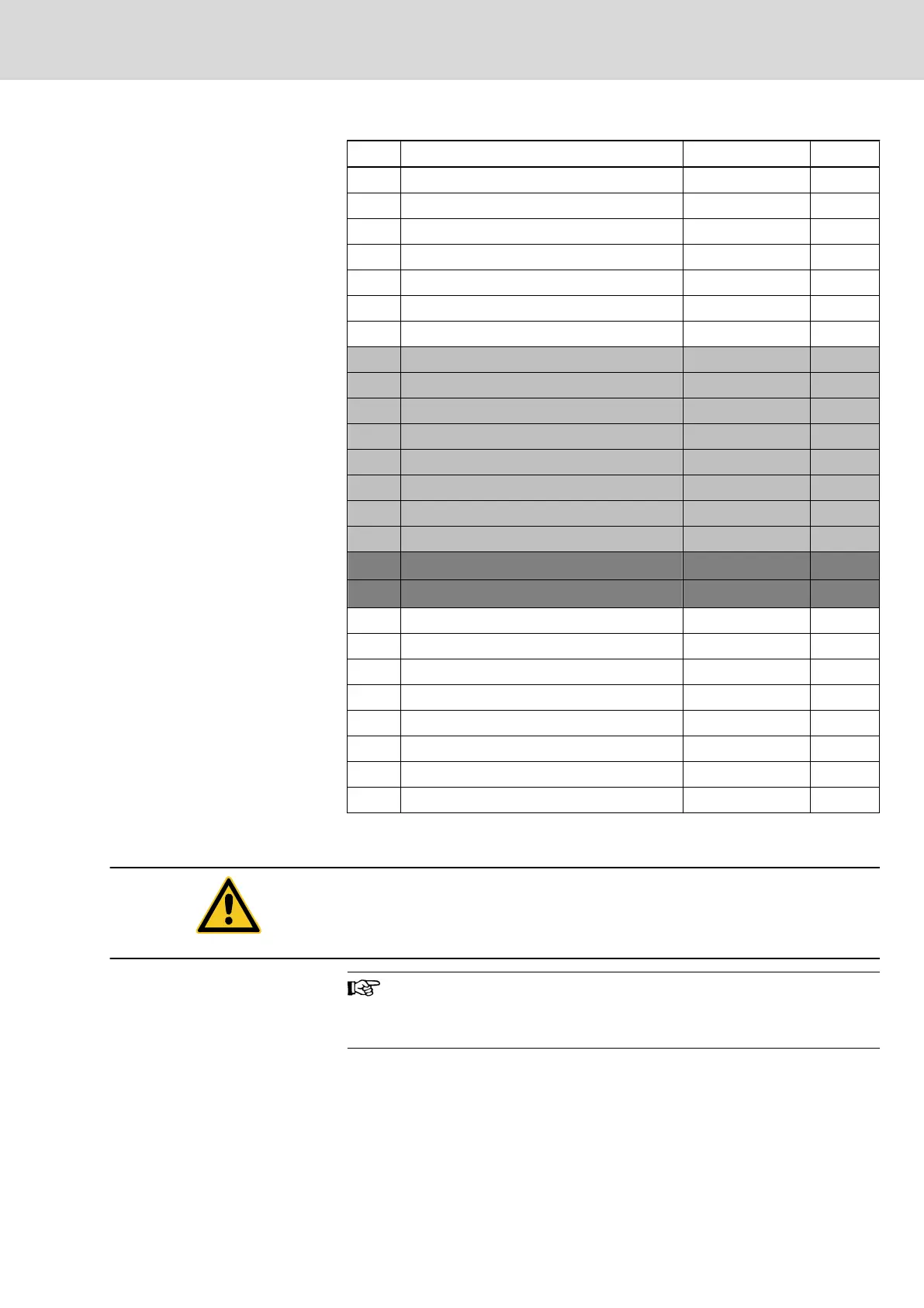
Pin Signal designation Type Signal
13 not assigned Output
14 not assigned Output
15 not assigned Output
16 not assigned Output
17 not assigned Output
18 not assigned Output
19 not assigned Output
20 Read enable Input 1
21 Processing enable Input 1
22 not assigned Input
23 not assigned Input
24 not assigned Input
25 not assigned Input
26 Feed enable all axes Input 1
27 E-STOP Input 0
28 GND (for input signals) U
external
29 GND (for input signals) U
external
30 not assigned Output
31 not assigned Output
32 not assigned Output
33 not assigned Output
34 not assigned Output
35 not assigned Output
36 not assigned Output
37 not assigned Output
* Input (addressable via analog C commands, see LINPOS)
1 Active signal level = High (1)
0 Active signal level = Low (0)
CAUTION
⇒ The EMERGENCY STOP contacts must always be laid out as NC contacts
so that they immediately stop all movements if a break occurs in the connecting
cables.
Signal level: 24 V DC, +/- 10% Max.
Load per output: 80 mA
Input current: approx. 5 mA
8.9.4 Installation
The NCIO card is always inserted in the UE1 slot. The interbus connection from
connector X23 of the NCM module to the connector X23.2 of the NCIO card is
to be plugged externally; the IKB0031 cable is included in the scope of delivery
of the BTV20.4A if the NCIO option is contained.
Project Planning Manual | Rexroth MTA 200 Electric Drives
and Controls
| Bosch Rexroth AG 103/135
NC Multifunction Card NCM02

 Loading...