Under normal operating conditions, the service life of the battery is 7 to 10 years.
Continuous charging of the battery does not affect its service life (continuous
operation of the control).
9.4.4 Status Displays and Error Diagnostics
Operating Status Display
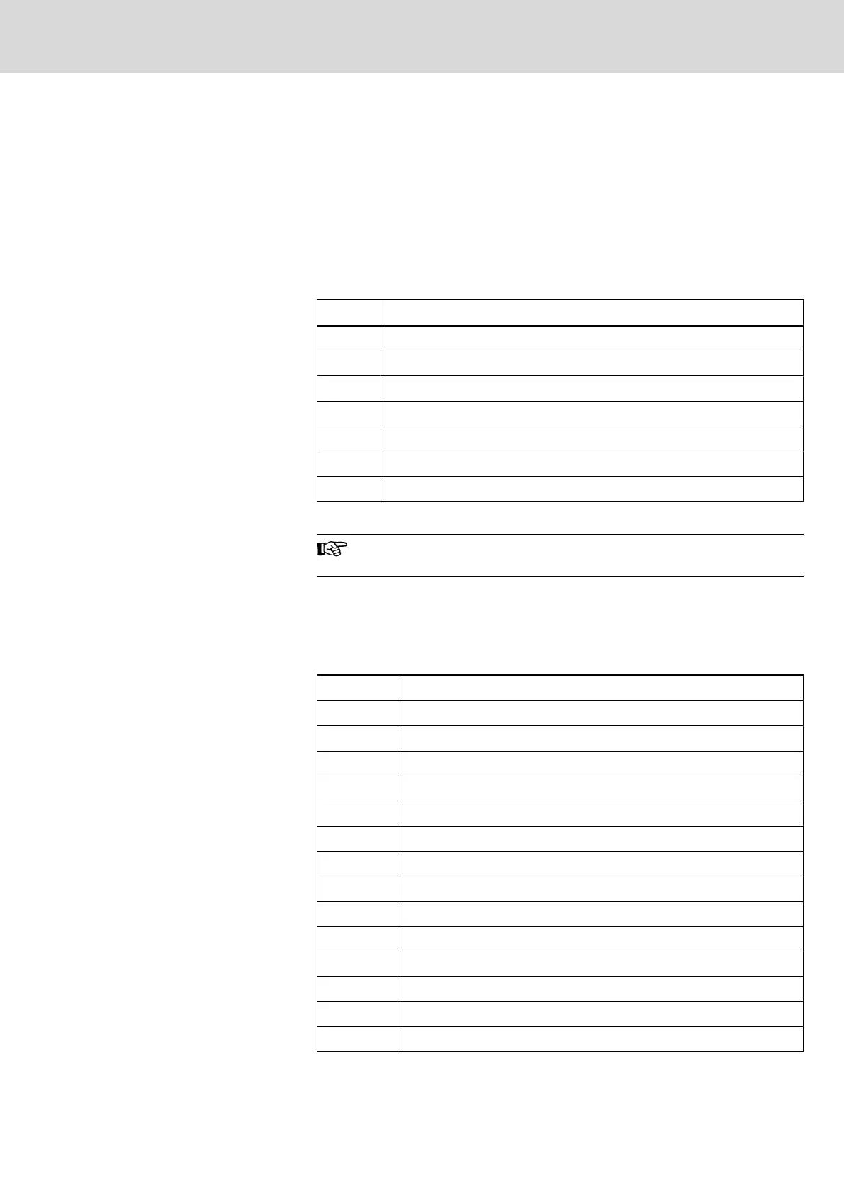
A diagnostic of the MTS-P0*.2 module can be performed using the 7-segment
display H1. The various states are displayed via the one-digit error codes shown
below.
Code Meaning
- Power-Fail triggered (control must be reset)
b Ready for operating (PLC is running)
0. Startup state (reset test)
F. Firmware in the flash EPROM is not valid
J. Boot lockout for firmware activated
S System stack overflow
P Local bus not connected
Fig.9-11: Operating states of MTS-P0*.2
If any other one-digit code (followed by a period) is displayed, cus‐
tomer service must be immediately notified.
Error Display
Error states are indicated by three-digit error codes on the successively flashing
7-segment display. The error codes represented correspond to the system error
messages of the user interface BOF/GBO.
Code Meaning
007 Software version error
008 Self-test was not successful
052 PLC program is not valid
055 Max. cycle time of PLC exceeded
071 Operating voltage of PLC too low
081 2-ms implementation time exceeded
082 INTERBUS error
083 INTERBUS storage overflow
084 INTERBUS configuration error
085 INTERBUS bus error
086 INTERBUS hardware firmware error
087 INTERBUS module error peripheral bus
088 INTERBUS not ready
089 INTERBUS - general error generation 4
Project Planning Manual | Rexroth MTA 200 Electric Drives
and Controls
| Bosch Rexroth AG 115/135
PLC Modules MTS-P01.2 and MTS-P02.2

 Loading...