sors and actuators as well as of intelligent field devices via INTERBUS. The
INTERBUS permits bridging of distances of up to 12.8 km (from the connection
point to the last connected remote bus user), divided into segments of up to
400 m.
LK IBM2 has the following characteristics:
● INTERBUS protocol (DIN E 19 258)
● up to 256 bus segments
● up to 16 user levels
● up to 512 users per configuration
● up to 4096 inputs and 4096 outputs per configuration (512 bytes)
● up to 32 INTERBUS loop users per bus segment
● CMD G4 support
The INTERBUS is configured and commissioned via the IBS CMD G4 Interbus
configurator (see DOK-CONTRL-IBS*CMD****-AW...) and the I/O editor of the
WinPCL programming interface (see DOK-CONTRL-WINPCL*6VRS-AW...).
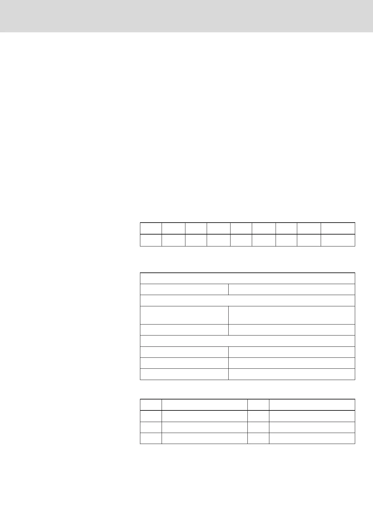
9.5.2 Setting of the I/O Address
DIP switch S1 must be set as follows (default setting) so that PCB IBM2 can
be addressed via the PC/104 bus::
1 2 3 4 5 6 7 8 Address
OFF OFF ON OFF OFF ON OFF OFF 120
h
Fig.9-18: Setting S1 DIP switch
9.5.3 Technical Data
Power supply
Operating voltage: +5VDC, 5% / 400 mA
Interface data
Communication interface: 2-wire remote bus, RS-422, without electrical iso‐
lation
Diagnosis interface: RS-232-C
Operating conditions
Surrounding air temperature: 0°C - +55°C
Humidity: -25°C - +70°C
Air pressure: max. 75% non-condensing
9.5.4 Interface Assignment
Pin Signal designation Pin Signal designation
1 NC 2 TxD - Transmit Data
3 RxD - Receive Data 4 NC
5 SGND - Ground 6 NC
Project Planning Manual | Rexroth MTA 200 Electric Drives
and Controls
| Bosch Rexroth AG 119/135
PLC Modules MTS-P01.2 and MTS-P02.2

 Loading...