Fig.4-34: USB interface
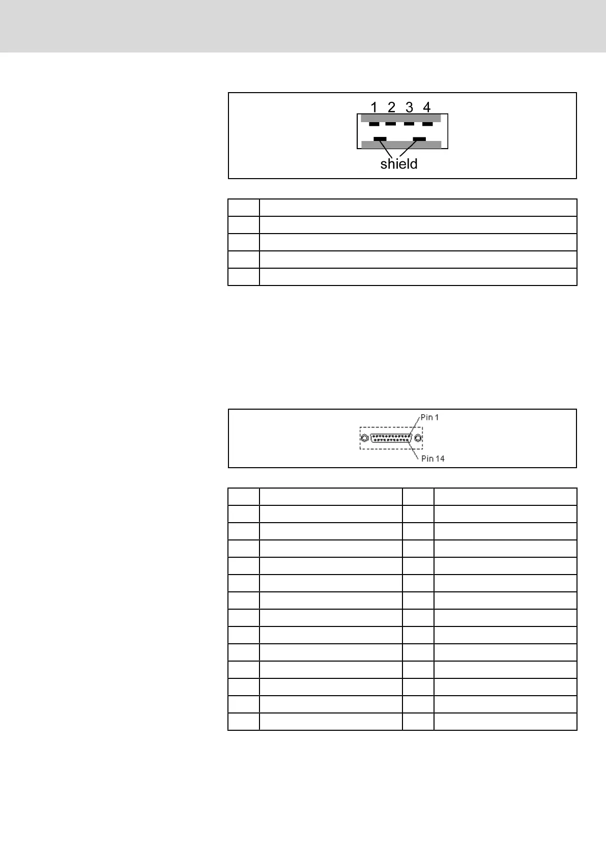
PIN Designation
1 USB power supply (max. 500 mA)
2 Data -
3 Data +
4 USB ground
Fig.4-35: Pin assignment of the USB interface
4.7.3 LPT1 Printer Interface and SIS
General Information
The serial interface COM2 (X16) is switched according to the Rexroth standard
(SIS). The LPT1 printer interface features the default Centronics assignment.
Both interfaces are explained more detailed in the following.
LPT1 interface
Fig.4-36: LPT1 interface
PIN Signal designation PIN Signal designation
1 /STB - Strobe 2 PD0
3 PD1 4 PD2
5 PD3 6 PD4
7 PD5 8 PD6
9 PD7 10 /ACK - Acknowledge
11 Busy 12 PE - Paper End
13 SLCT - Select 14 /AFD - Auto Feed
15 /ERR - Error 16 /INIT
17 /SLCTIN - Select In 18 GND
19 GND 20 GND
21 GND 22 GND
23 GND 24 GND
25 GND
Fig.4-37: Pin assignment of the LPT1 interface
Project Planning Manual | Rexroth MTA 200 Electric Drives
and Controls
| Bosch Rexroth AG 47/135
Machine Operator Terminal BTV 20.4A

 Loading...