COM2 SIS interface
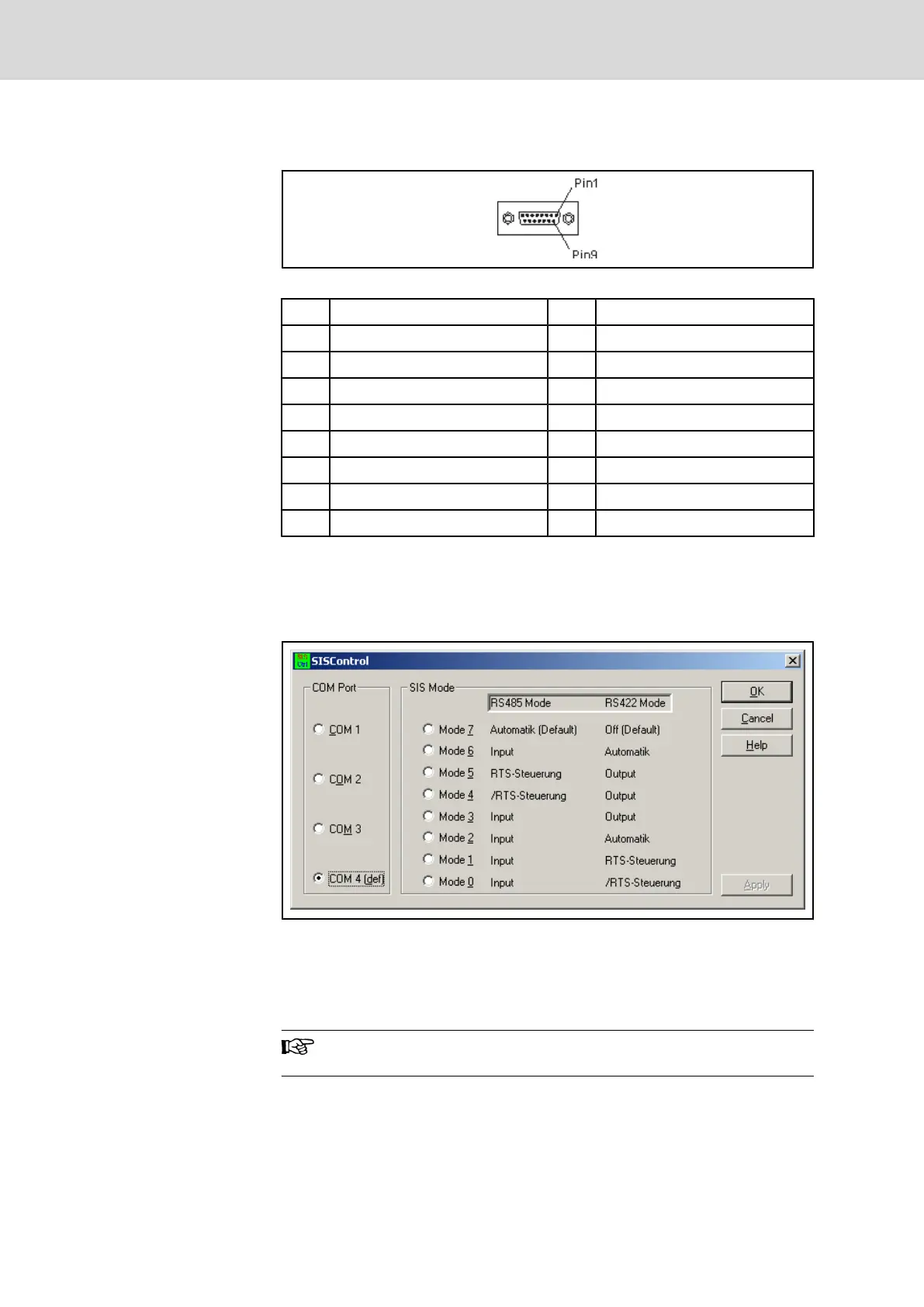
Fig.4-38: COM2 SIS interface
PIN Signal designation PIN Signal designation
1 Protected Ground 2 TxD (RS232)
3 RxD (RS232) 4 RS485+ / RxD+ (RS422)
5 RS485- /RxD- (RS422) 6 Data Set Ready (RS232)
7 Signal Ground 8 Data Carrier Detected (RS232)
9 TxD+ (RS422) 10 GND
11 TxD- (RS422) 12 +5V
13 Request To Send (RS232) 14 Clear To Send (RS232)
15 Data Terminal Ready
Fig.4-39: Pin assignment of the COM2 SIS interface
Configuration
The configuration of the COM2 SIS interface is performed by the "SISCon‐
trol" Windows tool. A link to this tool is filed on the Windows desktop.
Fig.4-40: COM2 SIS interface configuration tool "SISControl"
The COM2 SIS interface is internally performed via the COM4 port. Therefore
select under COM port always COM4 port that is shown as default here. Then
select the desired SIS mode 0 to 7 from the table, corresponding to the used
RS485 or RS422 interface.
The RS232 mode of the COM2 SIS interface is always active, in‐
dependent from the selected settings for RS485 and RS422!
4.7.4 Internal Wiring
The inner part of the BTV 20.4A is illustrated in fig. 4-41 "Inside of the BTV
20.4A" on page 49. The figure shows how the plug-in cards are allocated and
48/135 Bosch Rexroth AG | Electric Drives
and Controls
Rexroth MTA 200 | Project Planning Manual
Machine Operator Terminal BTV 20.4A

 Loading...